700-Bubbler-Man Rev 12 13 Feb 2020
Page 15/51
BUBBLER INTERFACE AND MENUS
The front panel has a display and keypad which is used to configure the Bubbler. When power is
supplied, the start-up screen will display for about 5 seconds before the Status Screen is displayed.
After three minutes of inactivity, the display will enter low power mode and blank out. Pressing any
button on the keypad will display the status screen.
3.1 KEYPAD
The keypad consists of the following buttons used to navigate through the different screens and
menu items:
The keypad consists of the following buttons used to
navigate through the different screens and menu items:
Figure 3-1: Keypad
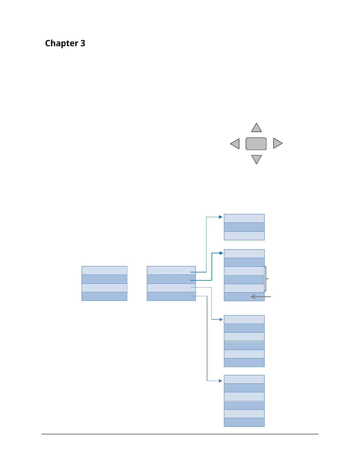
3.2 SCREENS, MENUS AND OPERATING THE USER INTERFACE
The following diagram illustrates the different screens and menus.
STATUS SCREEN*
MAIN MENU
Left
Select/
Accept
* Normally the Status screen
will display the Site’s name. If a
fault is detected, the Site name
will be replaced with FAULT:
followed by the type of fault (see
custom units (cu)
are indicated
Figure 3-2: Menu tree
Only shows if it is
a 4-20mA model