- 5 -
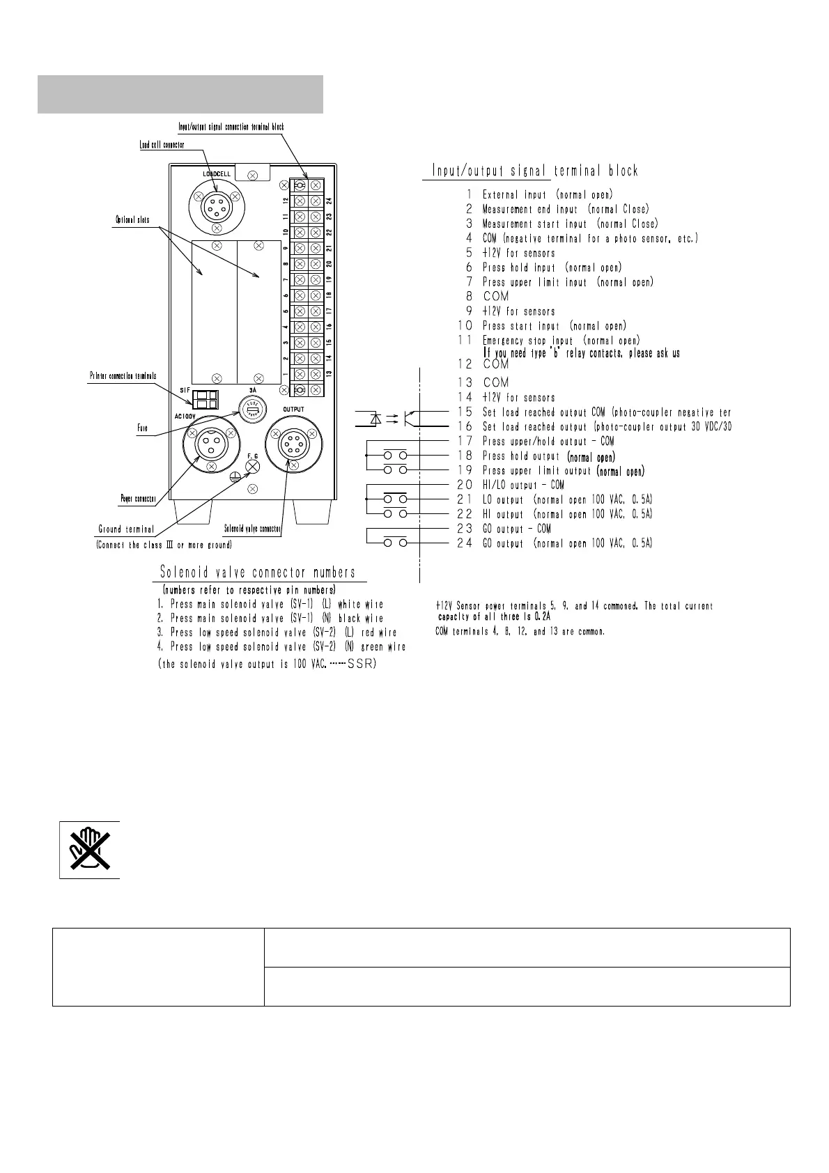
Press controller input/output
Terminal bases 1 to 14 are terminal bases for input signal connection. (Signal is non-voltage contact point or photo sensor)
1 - COM: External input – This is used for modes 4, 6. Input “a contact point”.
2 - COM: Measurement-end signal – Connect “b contact point.” (Usual: ON; activated: OFF) – Modes 5, 6 and 7 are used.
3 - COM: Measurement-start signal – Measurement does not start if it is short. Measurement is carried out when it is open.
(It is open from starting measurement to starting ram ascending)
6, 7, 10, 11 – COM: Input “a contact point” for all.
Press hold should be input while upper jig contacts with product after upper limit signal switches off.
However, this is not bottom dead center signal. Unless press lower limit signal is input, press control circuit
will not operate correctly in any mode. (Upper limit signal and hold limit signal MUST NOT be input
simultaneously)
Terminal bases 15 to 24 are terminal bases for output signal connection. Use them if necessary.
15, 16: Signal achieving setting
load (effective only during safet
y one process)
Modes 1 to 7; after starting, if setting load is achieved, the signal is output.
The output continues until reset or next start is applied.
Mode 9; after starting, if load is setting load or greater, the signal is output.
The output continues until reset or next start is applied.