- 11 -
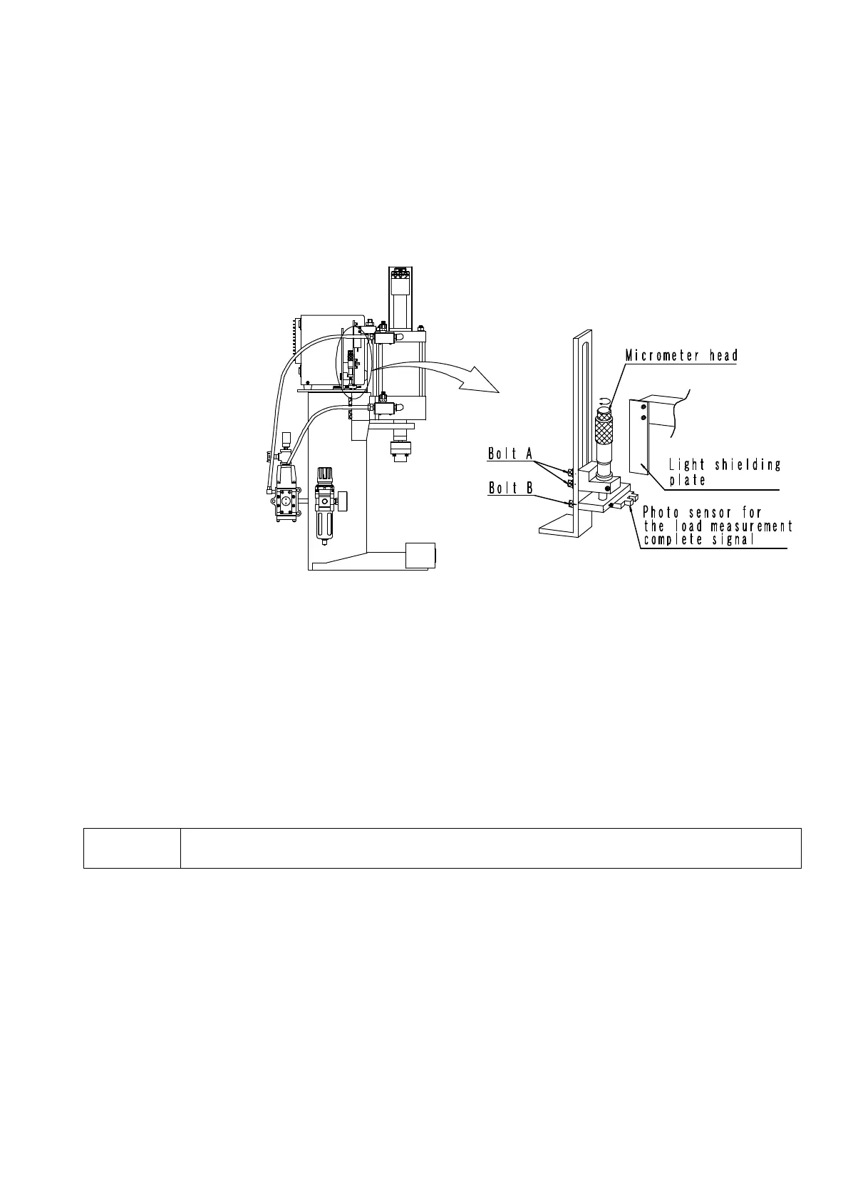
3.Position adjustment related to photo sensor for press-fit load measurement end signal
(1)Switch switching operation function of press controller should be switched to “Die matching.” Turn inching valve dial
so that inching valve is full close.
(2)Supply air pressure should be adjusted to 0.2MPa by turning regulator dial counterclockwise.
(3)Products for which press-fit is completed should be placed on lower die and upper die should be slowly descended by
carrying out inching operation and ram should be stopped in the state that product is completely depressed. When
ram stops completely, regulator is adjusted and supply pressure is reduced to 0.1MPa.
(4)Bolts A and B should be loosened and metal fitting for installing micro head should be vertically moved and fixed with
bolt A at the position near shade plate lower end where photo sensor operates.
Important: Sensor END lamp for press controller lights up if photo sensor for press-fit measurement end signal is activated.
Please adjust the photo sensor so that press-fit measurement end signal is input on after press hold sensor is
operated.
(5)Turn micro head dial and lower photo sensor until sensor END lamplight of press controller turns off. Slowly reverse
the micro head and raise photo sensor to the position at which sensor end lamplights up.
(6)Raise photo sensor about 0.3mm from the position at which sensor end lamplights up while reading scale of micro
head. (Because this prevents that it is not possible to measure press-fit pressure correctly when die conflicts with
product in final stage of press-fitting)
(7)Tighten bolt B so that photo sensor does not move.
(8)Turn inching valve dial so that inching valve is full open.
Warning
Do not bring body to press ram since the ram ascends when inching valve is fully opened.
Because there is a possibility of getting hurt.
(9)The adjustments related to photo sensor position are completed.