- 1 -
Name of each portion and functional description:
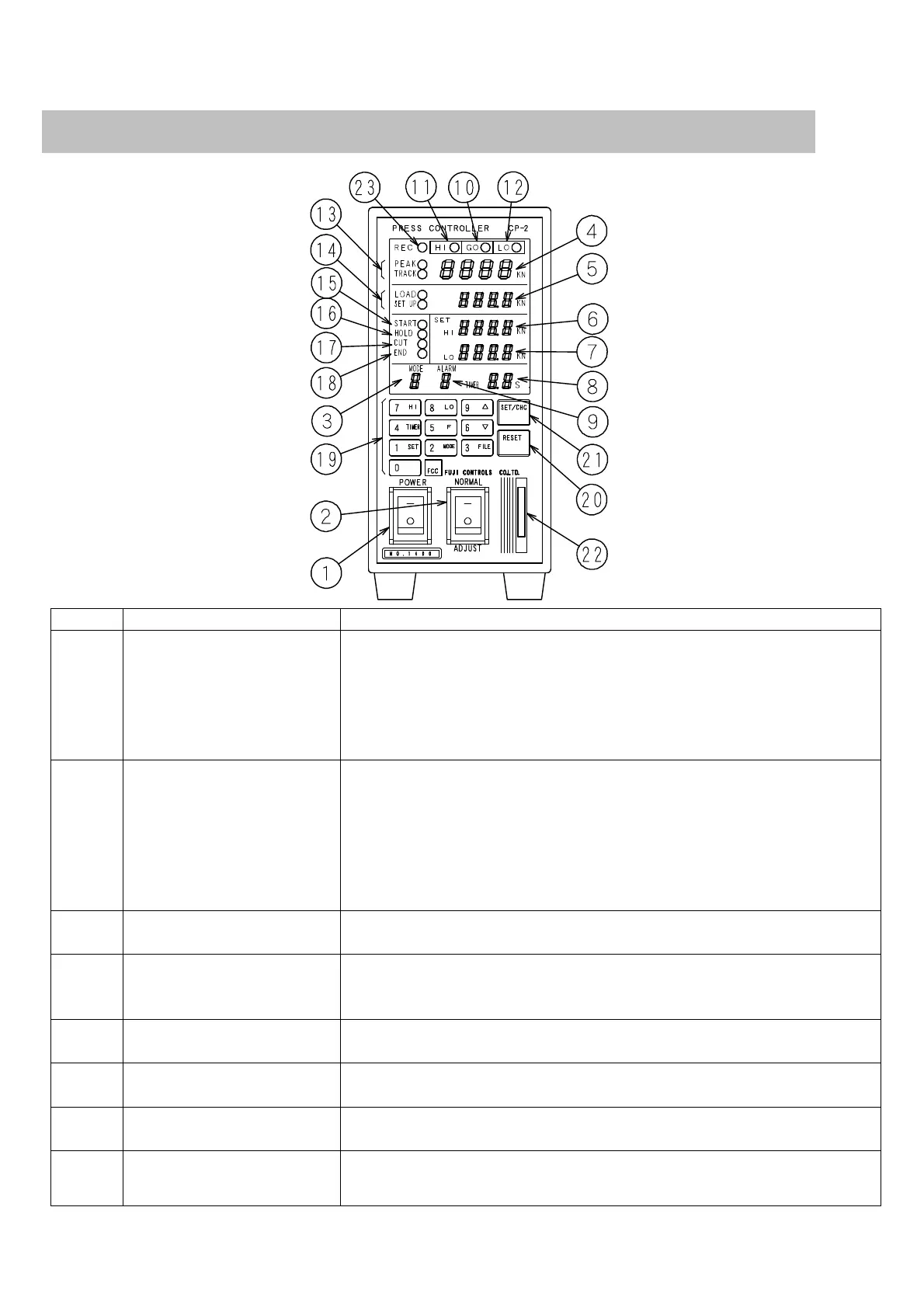
No. Name Functions
(1)
Power source
switch
Power enters when upper
side is pushed.
Electronic noise beeps and LED and ROM/RAM self-check is carried out fo
r nine seconds when power source switch is turned on. (It is not possible t
o operate during checking)
(2)
Switch - switching operation f
unction
When upper side is pushed, “safety one process operation” is activated. Whe
n lower side is pushed, “die matching operation” is activated.
Safety one process: This is a normal operation. Press operates one process
and judges loads while comparing when inputting press start signal.
Die matching: Only press function is operative. The “comparison judgment”
and “various controls” of press controller original functions do not work.
Please refer to “die matching” in page 7.
(3)
Control mode display portion
Setting mode Nos. are displayed. [1] to [9]
The [-] is displayed when the above (2) switch is “die matching.”
(4)
Display portion for value of
final loads or press-fit loads
Value of loads which are judged while comparing is displayed. (The value i
s displayed when measuring)
Display details change depending on mode being used.
(5)
Setting load display portion
Final load display portion
Products setting loads or final loads for post-judgment are displayed. (Thes
e are not displayed in modes 2 and 4)
(6)
Upper limit comparison value
display portion
Upper limit comparison value related to loads for press-fitting or crimping
(7)
Lower limit comparison value
display portion
Lower limit comparison value related to loads for press-fitting or crimping
(8)
Pressurizing time display
portion
Pressurizing time in timer mode (this is not displayed in modes 1, 7 and 9)