5-49
The table below lists functions that can be assigned to terminals [Y1], [Y2], and [30A/B/C].
To make the explanations simpler, the examples shown below are all written for the normal
logic (Active ON).
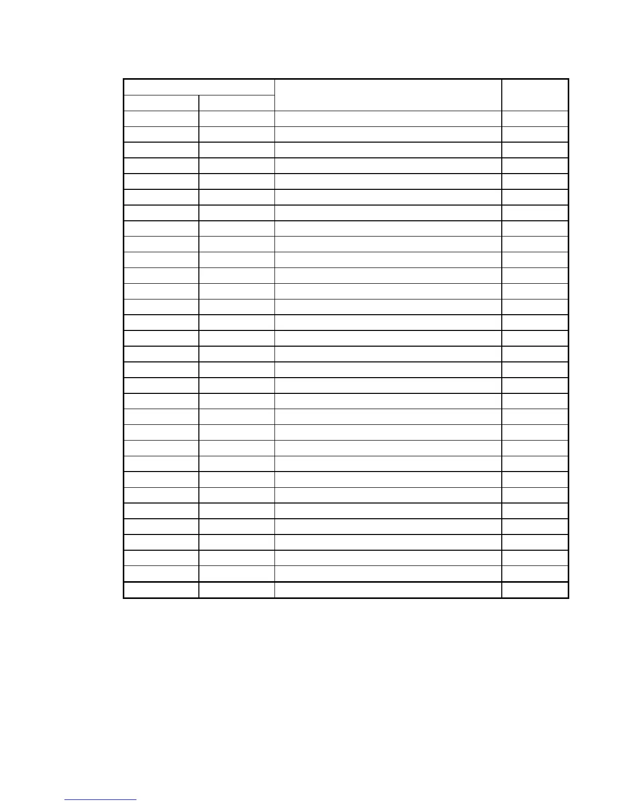
Function code data
Active ON Active OFF
Functions assigned Symbol
0 1000 Inverter running RUN
1 1001 Frequency arrival signal FAR
2 1002 Frequency detected FDT
3 1003 Undervoltage detected (Inverter stopped) LU
4 1004 Torque polarity detected B/D
5 1005 Inverter output limiting IOL
6 1006 Auto-restarting after momentary power failure IPF
7 1007 Motor overload early warning OL
10 1010 Inverter ready to run RDY
21 1021 Frequency arrival signal 2 FAR2
22 1022 Inverter output limiting with delay IOL2
26 1026 Auto-resetting TRY
27 1027 Universal DO U-DO *
1
28 1028 Heat sink overheat early warning OH
30 1030 Service lifetime alarm LIFE
33 1033 Reference loss detected REF OFF
35 1035 Inverter output on RUN2
36 1036 Overload prevention control OLP
37 1037 Current detected ID
38 1038 Current detected 2 ID2
42 1042 PID alarm PID-ALM
49 1049 Switched to motor 2 SWM2
56 1056 Motor overheat detected by thermistor (PTC) THM *
1
57 1057 Brake signal BRKS
59 1059 Terminal [C1] wire break C1OFF *
1
76 1076 PG error detected PG-ERR *
2
80 1080 Stop position override alarm OT *
2
81 1081 Timer output TO *
2
82 1082 Positioning completed PSET *
2
83 1083 Current position count overflowed POF *
2
99 1099 Alarm output (for any alarm) ALM
Inverter running -- RUN (Function code data = 0)
This output signal tells the external equipment that the inverter is running at a starting
frequency or higher. It comes ON when the output frequency exceeds the starting frequency,
and it goes OFF when it is less than the stop frequency. It is also OFF when the DC braking is
in operation.
If this signal is assigned in negative logic (Active OFF), it can be used as a signal indicating
"Inverter being stopped."