5-52
Brake signal -- BRKS (Function code data = 57)㩷
This signal outputs a brake control command that releases or activates the brake. Refer to the
descriptions of J68 through J72.
Alarm output (for any alarm) -- ALM (Function code data = 99)㩷
This output signal comes ON if any of the protective functions is activated and the inverter
enters Alarm mode.
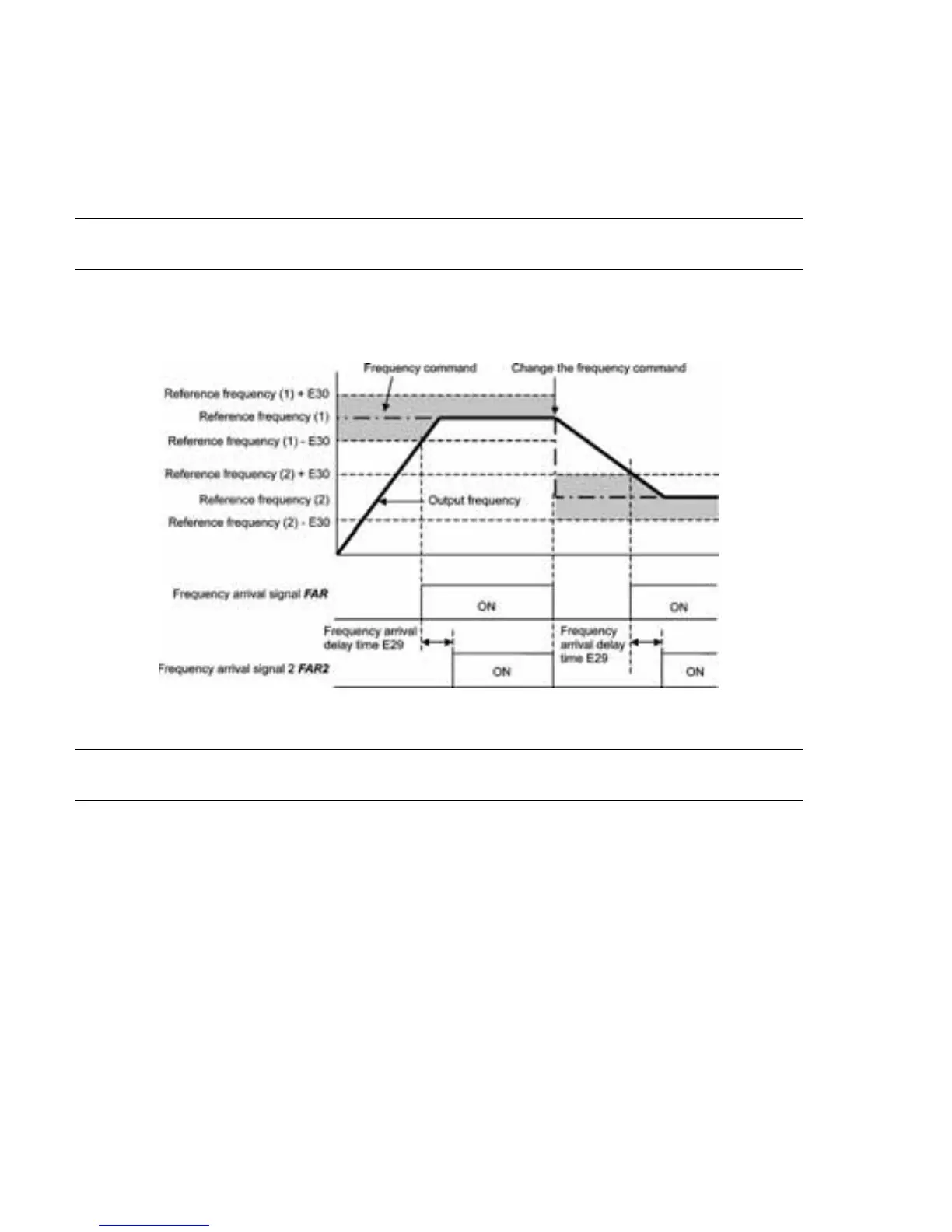
E29
E30
Frequency Arrival Delay Time (for FAR2)
Frequency Arrival (Hysteresis width for FAR and FAR2)
The moment the output frequency reaches the zone defined by "Reference frequency r
Hysteresis width specified by E30," the "Frequency arrival signal" FAR comes ON.
After the delay time specified by E29, the "Frequency arrival signal 2" FAR2 comes ON.
For details about the operation timings, refer to the graph below.
E34, E35
E37, E38
Overload Early Warning/Current Detection (Level and Timer)
Current Detection 2 (Level and Timer)
These function codes define the detection level and time for the "Motor overload early
warning" OL, "Current detected" ID, and "Current detected 2" ID2 output signals.
Motor overload early warning signal -- OL
The OL signal is used to detect a symptom of an overload condition (alarm code
N
) of the
motor so that the user can take an appropriate action before the alarm actually happens.
The OL signal turns ON when the inverter output current has exceeded the level specified by
E34. In typical cases, set E34 data to 80 to 90% against F11 data (Electronic thermal overload
protection for motor 1, Overload detection level). Specify also the thermal characteristics of
the motor with F10 (Select motor characteristics) and F12 (Thermal time constant). To utilize
this feature, you need to assign OL (data = 7) to any of the digital output terminals.
Current detected and Current detected 2 signals -- ID and ID2
When the inverter output current has exceeded the level specified by E34 or E37 and it
continues longer than the period specified by E35 or E38, the ID or ID2 signal turns ON,
respectively. When the output current drops below 90% of the rated operation level, the ID or
ID2 turns OFF. (Minimum width of the output signal: 100 ms)
To utilize this feature, you need to assign ID (data = 37) or ID2 (data = 38) to any of digital
output terminals.