5-66
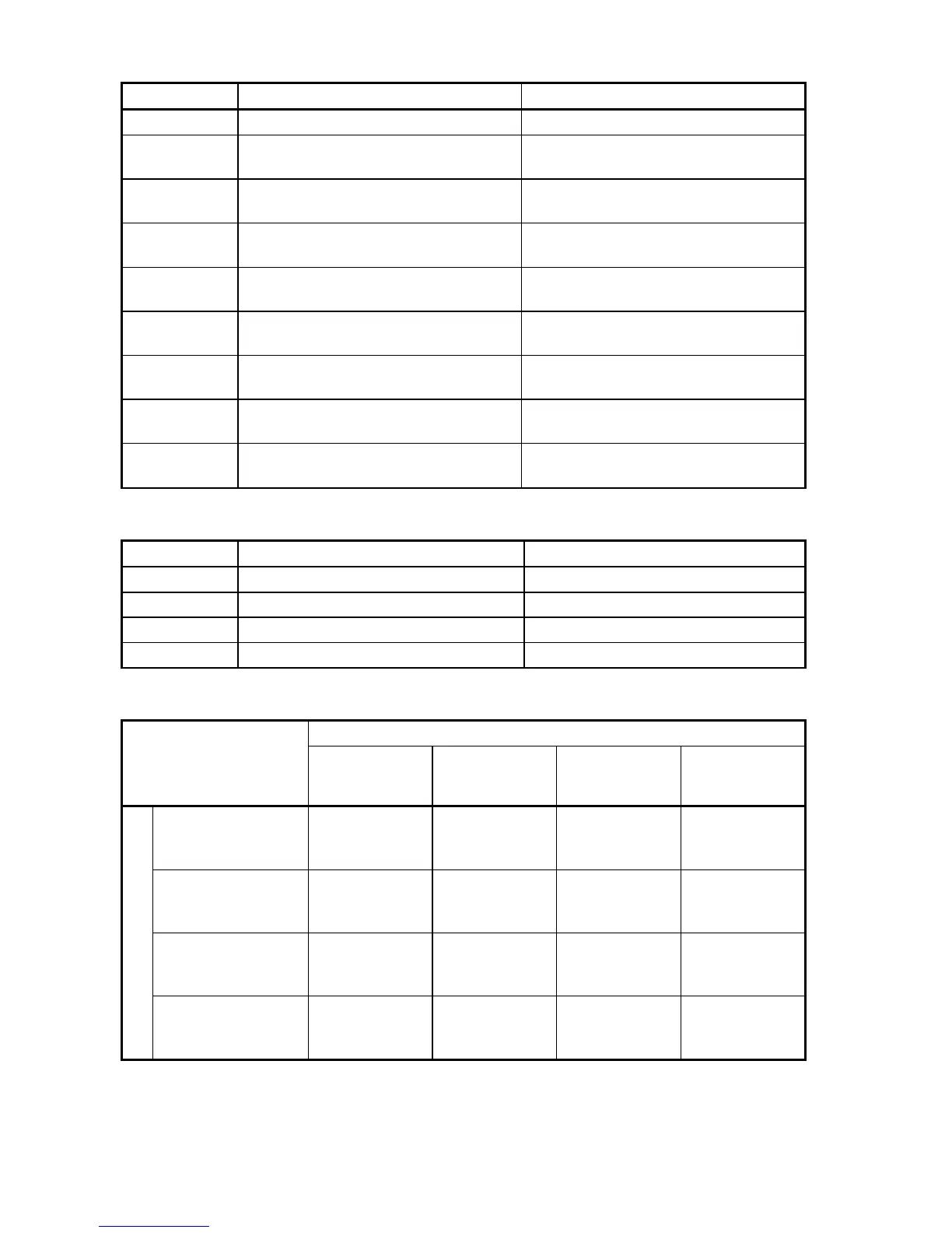
Command sources specified by H30 (Mode selection)
Data for H30 Frequency command Run command
0 Inverter itself (F01/C30) Inverter itself (F02)
1
Via RS-485 communications link
(standard)
Inverter itself (F02)
2 Inverter itself (F01/C30)
Via RS-485 communications link
(standard)
3
Via RS-485 communications link
(standard)
Via RS-485 communications link
(standard)
4
Via RS-485 communications link
(option card)
Inverter itself (F02)
5
Via RS-485 communications link
(option card)
Via RS-485 communications link
(standard)
6 Inverter itself (F01/C30)
Via RS-485 communications link
(option card)
7
Via RS-485 communications link
(standard)
Via RS-485 communications link
(option card)
8
Via RS-485 communications link
(option card)
Via RS-485 communications link
(option card)
Command sources specified by y98
Data for y98 Frequency command Run command
0 Follow H30 data Follow H30 data
1 Via field bus (option) Follow H30 data
2 Follow H30 data Via field bus (option)
3 Via field bus (option) Via field bus (option)
Combination of command sources
Frequency command
Inverter itself
Via RS-485
communications
link (standard)
Via RS-485
communications
link (option card)
Via field bus
(option)
Inverter itself
H30 = 0
y98 = 0
H30 = 1
y98 = 0
H30=4
y98=0
H30=0 (1 or 4)
y98=1
Via RS-485
communications link
(standard)
H30 = 2
y98 = 0
H30 = 3
y98 = 0
H30=5
y98=0
H30=2 (3 or 5)
y98=1
Via RS-485
communications link
(option card)
H30 = 6
y98 = 0
H30 = 7
y98 = 0
H30=8
y98=0
H30=6 (7 or 8)
y98=1
Run command source
Via field bus
(option)
H30 = 0 (2 or 6)
y98 = 2
H30 = 1 (3 or 7)
y98 = 2
H30 = 4 (5 or 8)
y98 = 2
H30 = 0 (1 to 8)
y98 = 3
For details, refer to the FRENIC-Multi User's Manual, Chapter 4 "BLOCK DIAGRAMS
FOR CONTROL LOGIC" and the RS-485 Communication User's Manual or the Field
Bus Option Instruction Manual.