2-20
Table 2.9 Symbols, Names and Functions of the Control Circuit Terminals (Continued)
Classifi-
cation
Symbol
Name Functions
Analog output
Analog
monitor
(FMA
function)
The monitor signal for analog DC voltage (0 to +10 V) is output. You can
select FMA function with slide switch SW6 on the interface PCB, and change
the data of the function code F29.
You can also select the signal functions following with function code F31.
• Output frequency 1 (Before slip compensation)
• Output frequency 2 (After slip compensation)
• Output current • Output voltage • Output torque
• Load factor • Input power • PID feedback amount (PV)
• PG feedback value • DC link bus voltage • Universal AO
• Motor output • Calibration • PID command (SV)
• PID output (MV)
* Input impedance of external device:
Min. 5k: (0 to +10 VDC output)
* While the terminal is outputting 0 to +10 VDC, it is capable to drive up to
two meters with 10k: impedance.
(Adjustable range of the gain: 0 to 300%)
[FM]
Pulse
monitor
(FMP
function)
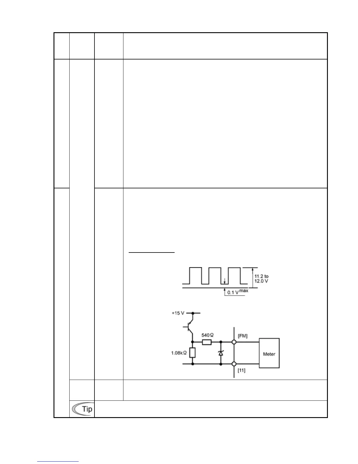
Pulse signal is output. You can select FMP function with the slide switch
SW6 on the interface PCB, and change the data of the function code F29.
You can also select the signal functions following with function code F31.
* Input impedance of the external device: Min. 5k:
* Pulse duty: Approx. 50%
Pulse rate: 25 to 6000 p/s
Voltage waveform
• Pulse output waveform
• FM output circuit
[11]
Analog
common
Two common terminals for analog input and output signal terminals
These terminals are electrically isolated from terminals [CM]s and [CMY].
Pulse output
Do not connect a meter with pull-up resistor to the input (primary) side.