6. SYSTEM DESIGN
PIPE CONNECTION
WARNING
Be sure to perform flare connection. It causes a malfunction and a fire of this unit when connecting
the pipes other than flare connection (brazing etc.).
(1) Detach the caps and plugs from the pipes.
CAUTION
Be sure to apply the pipe against the port on the unit correctly. If the centering is improper, the flare
nut cannot be tightened smoothly. If the flare nut is forced to turn, the threads will be damaged.
Do not remove the flare nut from the pipe until immediately before connecting the connection pipe.
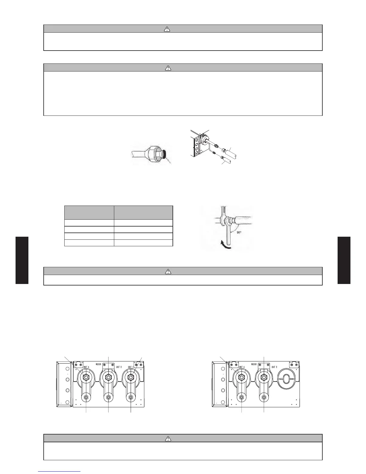
Hold the torque wrench at its grip, keeping it in the right angle with the pipe, in order to tighten the
flare nut correctly.
entering the pipe against port on the unit turn the are nut with our hand.
Connection
pipe (Gas)
Connection
pipe (Liquid)
To prevent gas leakage, apply the
refrigeration compressor oil (or
equivalent) used for the outdoor unit to
the are surace.
hen the are nut is tightened proper b our hand use a torue wrench to na tighten it.
Flare nut
[mm (in.)]
Tightening torque
[N·m]
6.35 (1/4) dia. 16 to 18
9.52 (3/8) dia. 32 to 42
12.70 (1/2) dia. 49 to 61
15.88 (5/8) dia. 63 to 75
Do not remove the cap from the connection pipe before connecting the pipe.
CAUTION
Be sure to connect the large pipe after connecting the small pipe completely.
(4) Branch box is marked with engraved letters indicating each corresponding indoor unit (UNIT A,
UNIT B and UNIT C).
UNIT A : Refrigerant pipe connection port for UNIT A
UNIT B : Refrigerant pipe connection port for UNIT B
UNIT C : Refrigerant pipe connection port for UNIT C
UNIT A
(gas pipe)
UNIT A
(liquid pipe)
UNIT B
(liquid pipe)
UNIT B
(gas pipe)
[2 branches type]
UNIT A
(gas pipe)
UNIT A
(liquid pipe)
UNIT B
(liquid pipe)
UNIT C
(liquid pipe)
UNIT B
(gas pipe)
UNIT C
(gas pipe)
[3 branches type]
CAUTION
Label all the refrigerant piping (liquid pipe, gas pipe) specifying to which indoor units they will be
connected.
Body side
Holding spanner
Torque wrench
- (06 - 36) -
SYSTEM
DESIGN
SYSTEM
DESIGN
 Loading...