EasyManua.ls Logo

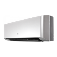
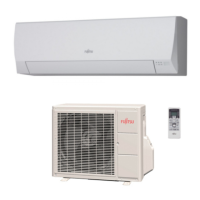
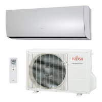
Fujitsu ASYG12LMCA

Fujitsu ASYG12LMCA
425 pages
To Next Page IconTo Next Page
To Previous Page IconTo Previous Page
Loading...
¢
System diagram
1 remote controller:
A
Indoor unit
Remote controller
2 remote controllers:
Primary
Secondary
BC
Indoor unit
Remote controllers
A, B, C: Remote controller cable
A ≤ 500 m;B + C ≤ 500 m
¢
Electrical wiring
1 remote controller:
Remote controller
1 (Red): 12 V
2 (White): Signal
3 (Black): COM
Indoor unit
Remote
controller
123
123
2 remote controllers:
Remote controllers
1 (Red): 12 V
2 (White): Signal
3 (Black): COM
Primary Secondary
Indoor unit
123
123 123
Remote
controller
¢
Controller combination
As for the combined usage of the controller, refer to following figures.
Good
UTY-RVNYM UTY-RNNYM UTY-RVNYM UTY-RSNYM
Indoor unit
UTY-RVNYM
SET TEMP.
START/STOP
Indoor unit
Indoor unit
UTY-RVNYM
- 179 -
MULTI TYPE
5, 6 ROOMS TYPE

Table of Contents

Other manuals for Fujitsu ASYG12LMCA

Related product manuals