Management Unit Rear of the MU
U41858-J-Z126-2-76 59
Dokuschablonen 19x24 Version 7.4us für FrameMaker V7.x vom 09.02.2010 © cognitas GmbH 2001-2010
Dokuschablonen 19x24 Version 7.4us für FrameMaker V7.x vom 09.02.2010 © cognitas GmbH 2001-2010
19. April 2017 Stand 15:41.40 Pfad: P:\FTS-BS\Server\SE-Server\SE-Doku\1303913_BA_Basis_update_2\prod_e\ba_basis.k06
Assignment of the PCIe slots
The assignment of the PCIe slots differs from MU M1 to MU M2.
PCIe slot assignment on an MU M1
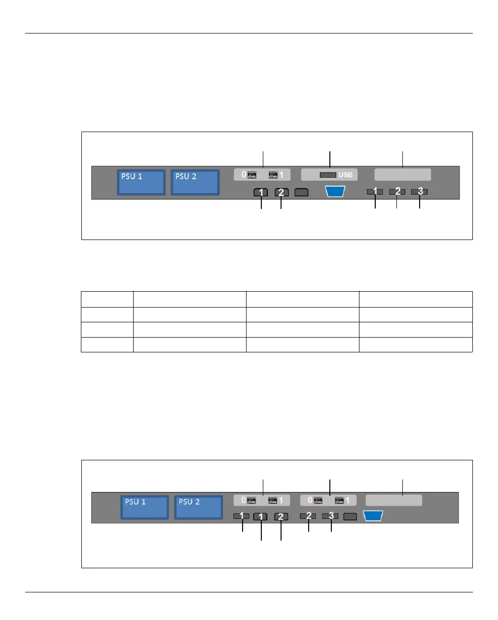
Figure 20: Principle of PCIe slot assignment at the rear of the device (MU M1)
The figure shows the PCIe slots of the MU M1 on an SE700. On the various model series
of the SE server, the PCIe slots of an MU M1 are assigned as follows:
The MU M1 can be equipped with a second FibreChannel card in the free PCIe slot S1.
Accordingly, two more ports are available for the ROBAR connection and cluster
functionality.
PCIe slot assignment on the MU M2
Bild 21: Principle of PCIe slot assignment at the rear of the device (MU M2)
PCIe slot SE700 SE500 SE300
S1 Not assigned. Not assigned. Not assigned.
S2 USB card USB card Not assigned.
S3 FibreChannel card FibreChannel card Not assigned.
Tabelle 2: PCIe slot assignment on an MU M1
S3 S1
(System LAN ports)
SYS1 SYS2
USB ports
S2
S4 S2
(USB ports)
S3
(System LAN ports)
SYS1 SYS2
USB2 USB3 USB1
 Loading...