28 Operating Manual RX2530 M5
3.3.1.2 Server rear
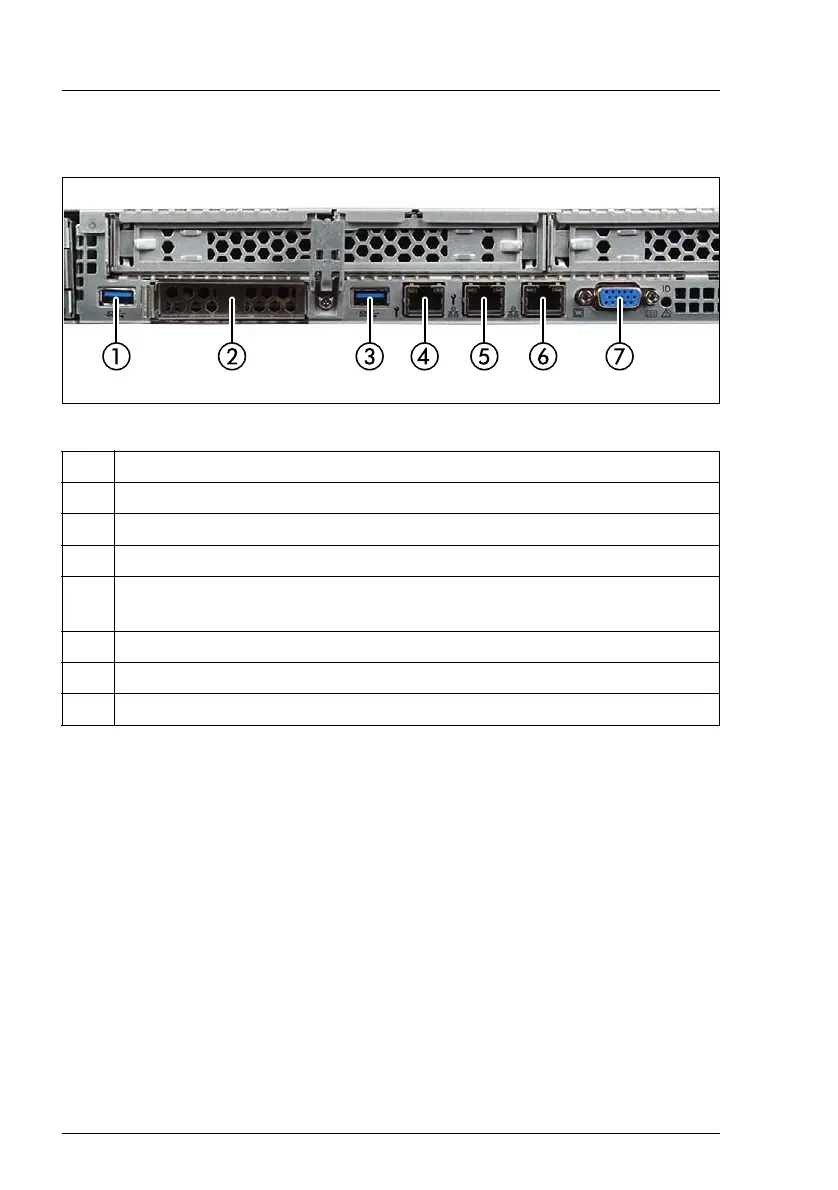
Figure 4: Connectors on the rear
The corresponding indicators are explained in section "Indicators on the server
rear" on page 38.
I Depending on the BIOS settings, the shared LAN connector may also be
used as a management LAN connector. For more information, see the
corresponding BIOS Setup Utility reference manual.
I Some of the devices connected require special software (e.g. drivers)
(see documentation for the connected device).
Pos. Description
1 USB 3.0 connector
2 OCP module (optional, different variants)
3 USB 3.0 connector
4 Management LAN connector (for iRMC S5 server management
function)
5 Shared LAN connector (LAN1)
6 LAN connector (LAN2)
7 Video connector (VGA)

 Loading...


