36 Service Supplement TX150 S6
Replacing the system board Replacement routines
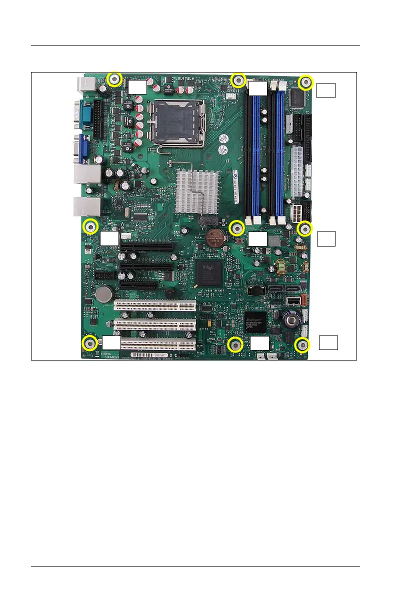
Figure 19: Position of the screws
Ê Remove the 9 screws from the system board.
Ê Lift the system board slightly using the socket of PCI slot 5, thereby you lift
the system board out of the centre rings of the spacer bolts.
Ê Carefully lift the system board (using both hands) out of the chassis in a
slight angle. Thereby you pull the connectors out of the connector panel.
V CAUTION!
Always take the system board with both hands!
Never lift the system board one-sided or at the heat sink, because
the solder connections between the socket and the system board
come under tension and increase the risk of damage and
malfunction!
1
2
3
4
5
6
7
8
9
 Loading...