12
10. Lower shaft (5) completely and fasten hex. socket bolt (23) and (26)
11. Lower the transducer by turning the handle until the transducer case (6) touches the hull
flange (3).
12. Confirm that the hull plate projects by 24 mm.
Note: Never weld the hull flange or transducer tank when the transducer is being fitted, nor
weld near the transducer of other equipment.
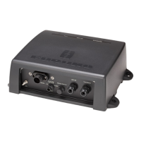
1.5 Distribution Box
The distribution box can be mounted on the deck or on a bulkhead.
Consider the following points when selecting a mounting location.
• Select a location which is both well ventilated and low in humidity to keep the unit cool.
• The unit weighs 12 kg. For bulkhead mounting, be sure the mounting location is strong
enough to support the weight under the continued vibration normally encountered on the
vessel.
• A magnetic compass will be affected if the distribution box is too close. Observe the
compass safe distances to prevent disturbance to the magnetic compass.
Fasten the distribution box with four tapping screws (6X30, supplied).
Refer to the outline drawing at the end of this manual for mounting dimensions.
For bulkhead mounting;
1. Tighten lower tapping screws so there is 5 mm clearance between bottom of screw head
and bulkhead.
2. Screw slots of the unit with the tapping screws tightened at step 1.
3. Fasten the unit with upper tapping screws.

 Loading...