24
20S0251
(for display unit, digital indicator/distance indicator)
• Locate the fuse of the cable inside the terminal box.
• Tape the drain wire, and fix the earth terminal in the terminal box.
• Outer sheath should be fixed in the cable clamp.
65S1231
(for display unit, digital indicator/distance indicator)
Strip the outer sheath by 120 mm, and fasten it by the clamp. Attach the climp-on lug FV0.5-4 to
each core.
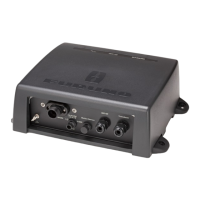
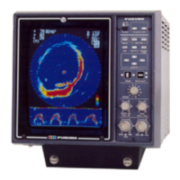
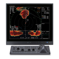
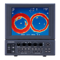
2.5 Display Unit
(Digital Indicator, Distance Indicator)
Use the cable assemblies MJ-A7SPF0009-020 and MJ-A6SPF0013-020 (supplied).
Connect the cable at the rear of the display unit, and fabricate the other end of the cable for
connection to the terminal box. Refer to the interconnection diagram at the end of this manual.
2.6 Dimmer, Analog Display Unit, Range Switch
Box
See the schematic diagram at the back of this manual.
Range switch box
TTYCY-2S
DPYCY-1.25
DPYCY-1.25
DPYCY-1.25
Dimmer
Analog display

 Loading...