1. MOUNTING THE UNIT
6
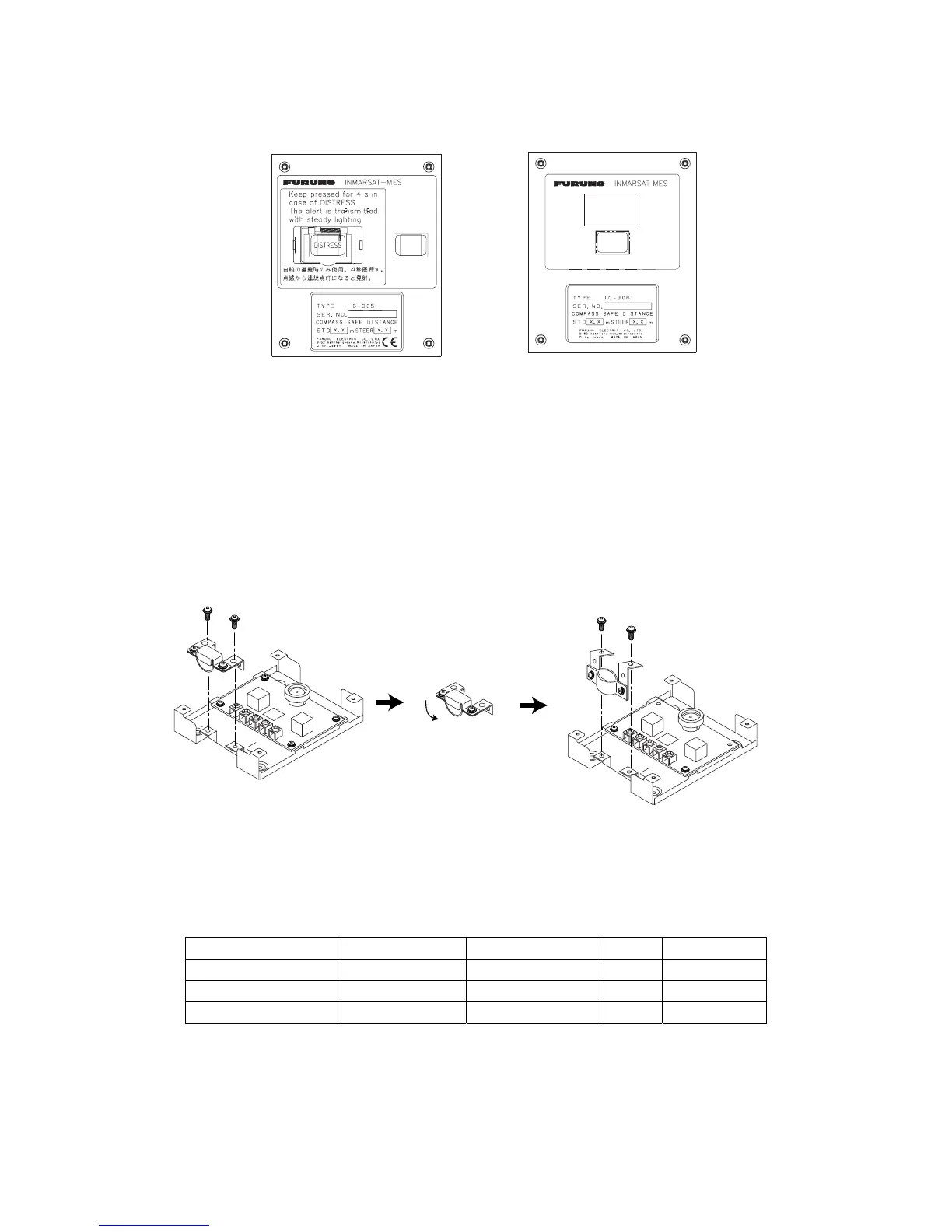
1.3 Distress Alert/Received Call Unit IC-305/
Alarm Unit IC-306
Distress alert/received call unit IC-305
Alarm unit IC-306
ALARM
ACK
ALARM
ACK
Bulkhead mounting
1. Remove four screws from the unit to separate the bottom chassis from the top cover.
2. Fix the bottom chassis to the mounting location with four tapping screws (supplied).
3. Cable can be entered from bottom or rear panel. Select suitable entrance. For rear
panel entrance, change the clamp orientation as follows.
a) Unfasten two screws to remove the cable clamp.
b) Turn the clamp 90 degrees.
c) Refasten two screws removed at step a) to fix the clamp.
Unfasten these screws.
Rotate.
Refasten screws.
Cable clamp, rotating
4. Run the interconnection cable thru a cable entrance and connect it to terminal board.
Flush mounting
The optional flush mounting kit OP16-27 (Code No. 004-448-000) is required.
Name Type Code No. Qty Remarks
Fixture 16-018-4201-1 100-317-841 1
Pan head screw M3x6 000-800-362 4
Self-tapping screw 4x16 000-162-605-10 4
1. Cut out the mounting position referring to the outline drawings at the back of this
manual.
2. Fix the unit to the fixture with four pan head screws (supplied as the option kit).
3. Fasten four tapping screws (ø5, supplied as the option kit) to mount the fixture to the
mounting position.