2. WIRING
15
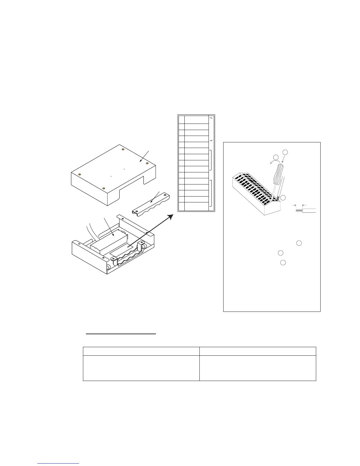
2.4 Junction Box IC-315
Use the junction box IC-315 to connect the distress alert/received call unit
IC-305 and other unit (max. four units) to the terminal unit.
Unfasten four screws to remove the box cover to connect cables.
For connection, use the optional 5 pair cable CO-SPEVV-SB-C 0.2x5P, JIS cable
(Japan Industrial Standards) TTYCS-4 or equivalent. When using the
CO-SPEVV-SB-C 0.2x5P cable, replace the cable clamp with the cable clamp
16-018-6008-1, supplied with IC-315.
Cover
Terminal
board
To terminal unit
Procedure
1. Insert driver from direction 1 .
2. Tilt slightly toward 2 .
3. Insert cable core to 3 .
Core 7 mm
1
2
3
Vcc
GND
TD/RD-A
TD/RD-B
NC
TD-A(NAV)
TD-B(NAV)
RD-A(NAV)
RD-B(NAV)
GND
DMC OUT-H
DMC OUT-C
DMC IN-H
DMC IN-C
DMC CTR
IC-305/306
1
2
3
4
5
6
7
8
9
10
11
12
13
14
15
Cable clamp
4. Pull out the driver.
Note 1: Do not insert the cable deeply
to prevent pinching the cable sheath.
Note 2: Pull the cable slightly to confirm
the tightening
Sticker for
connection of
other equipment
Junction Box IC-315
Input/output sentences
The following sentences can be input/output with the navigator connected.
Input sentences Output sentences
GGA, GLL, VTG, WPL, RMA, RMB,
RMC, MTW, DBT, BWC, BWR, VDR,
ZDA
GGA, ZDA, GLL, VTG, RMC, GSV
 Loading...