1. MOUNTING THE UNIT
2
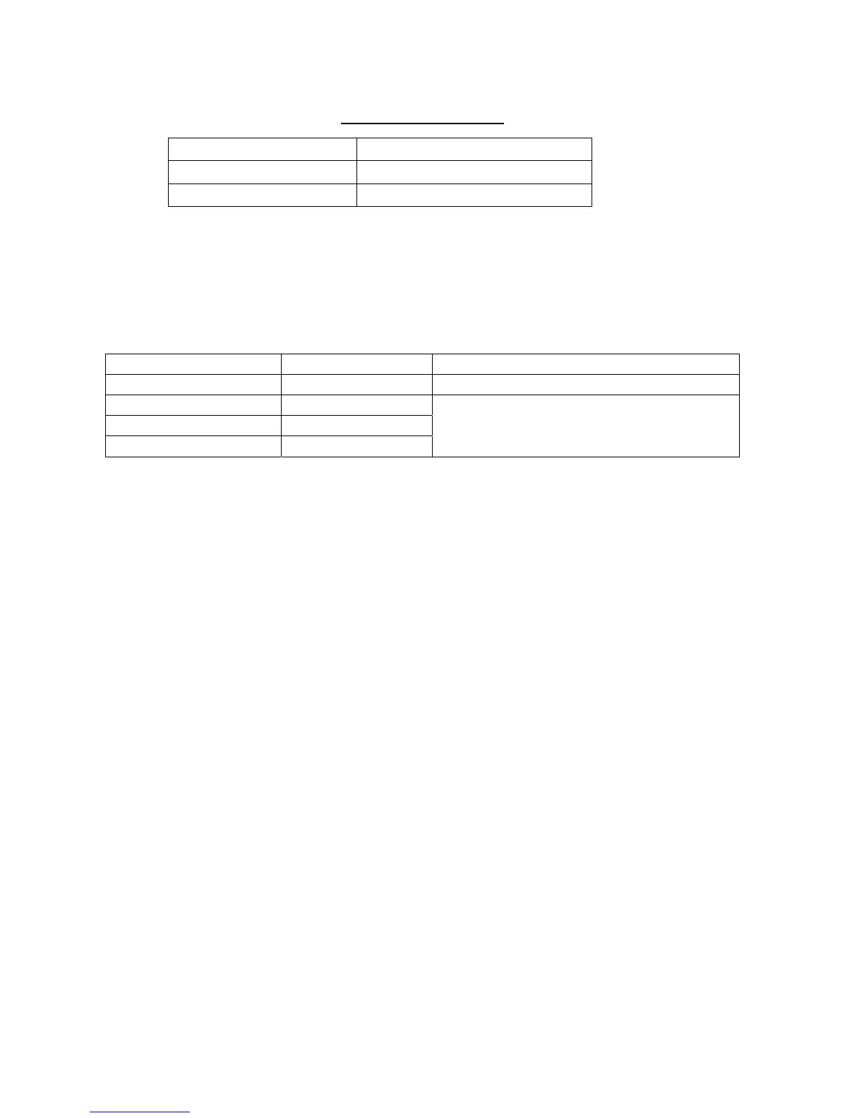
• The allowable vibration level as specified by Inmarsat is as shown in the table below.
Allowable vibration level
Frequency Level
2 to 10 Hz 2.54 mm Peak Amplitude
10 to 100 Hz 9.8 m/s² Peak Acceleration
• Avoid the location near funnels and stacks; smoke and soot on the radome can lower
signal level.
• Separate the antenna unit 5 m from HF, VHF or 27 MHz antenna.
Mounting
The antenna cable is available in lengths of 30 m, 50 m and 100 m (see table below).
Cable length Type Remarks
30 m (no armor) TP5FBAW-5DFB TNC connector at both ends
30 m (w/armor) 5D-FB-CV-NP
50 m (w/armor) 8D-FB-CV
100 m (w/armor) 12D-SFA-CV
N connector on one end (antenna side)
To mount the antenna unit, an exclusive pipe is necessary.
Note 1: Do not shorten these cables. Interference can result, affecting performance.
Note 2: To mount the antenna unit with the optional antenna mounting kit (Type:
CP16-03701, Code No.: 004-555-000), see page D-13.
Locally prepare an antenna mast with a ground stud (M6 stainless steel bolt welded to
antenna mast) and mounting pipe with threads and plate (See the outline drawing of the
mounting plate shown on the next page.) Weld the mounting pipe to the antenna mast.
The distance between the stud and the earth terminal on the antenna unit should be within
340 mm, which also is the length of the supplied earth wire.