Cell Connections
40
The cell cable connections used in Save Both Half Cells mode are shown in Table 5-2. The orange Counter
Sense lead must be connected.
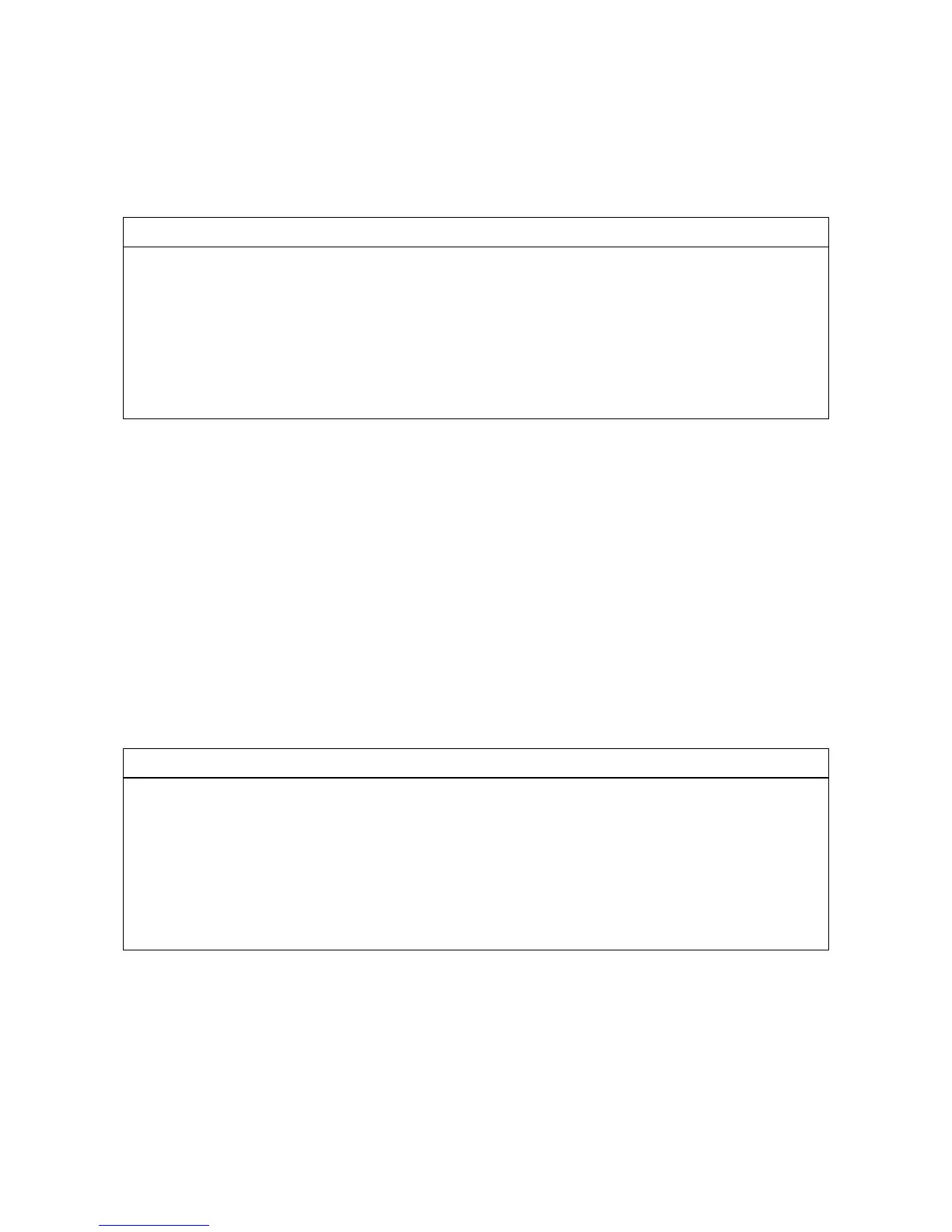
Table 5-2
Cell Cable Connections for Three-Electrode Battery Testing
Connect to positive battery terminal
Connect to positive battery terminal
Connect to the reference electrode
Connect to negative battery terminal
Connect to negative battery terminal
Leave open or connect to a Faraday shield
The voltage of the full cell is measured between the counter sense and the working sense leads.
The white pin jack on the cell cable is normally connected to a reference electrode. The potential between this
lead and the Working Sense lead is reported as the positive half-cell potential.
ZRA Mode Cell Connections
The Interface 5000 can function as a precision Zero Resistance Ammeter (ZRA). In this mode it maintains two
metal samples at the same potential and measures the current flow between the samples. It can also measure
the potential of the samples versus a reference electrode. The cell cable connections for ZRA mode are shown
in Table 5-3. The connections are very similar to those for the potentiostat and galvanostat modes.
In ZRA mode a second working electrode is substituted for the counter electrode, and the Orange Counter
Sense lead must be connected.
Table 5-3
Cell Cable Connections for ZRA Mode
Connect to metal sample #1
Connect to metal sample #1
Connect to a reference electrode
Connect to metal sample #2
Connect to metal sample #2
Leave open or connect to a Faraday shield
The counter sense and the working sense lead are each connected to different metal samples. In ZRA mode,
the Interface 5000 is normally programmed to maintain zero volts between these leads. It therefore maintains
the two metal samples at the same voltage.
The white pin jack on the cell cable is normally connected to a reference electrode. The potential between this
lead and the working sense lead is reported as the cell potential.