Appendix C: I/O Connectors
69
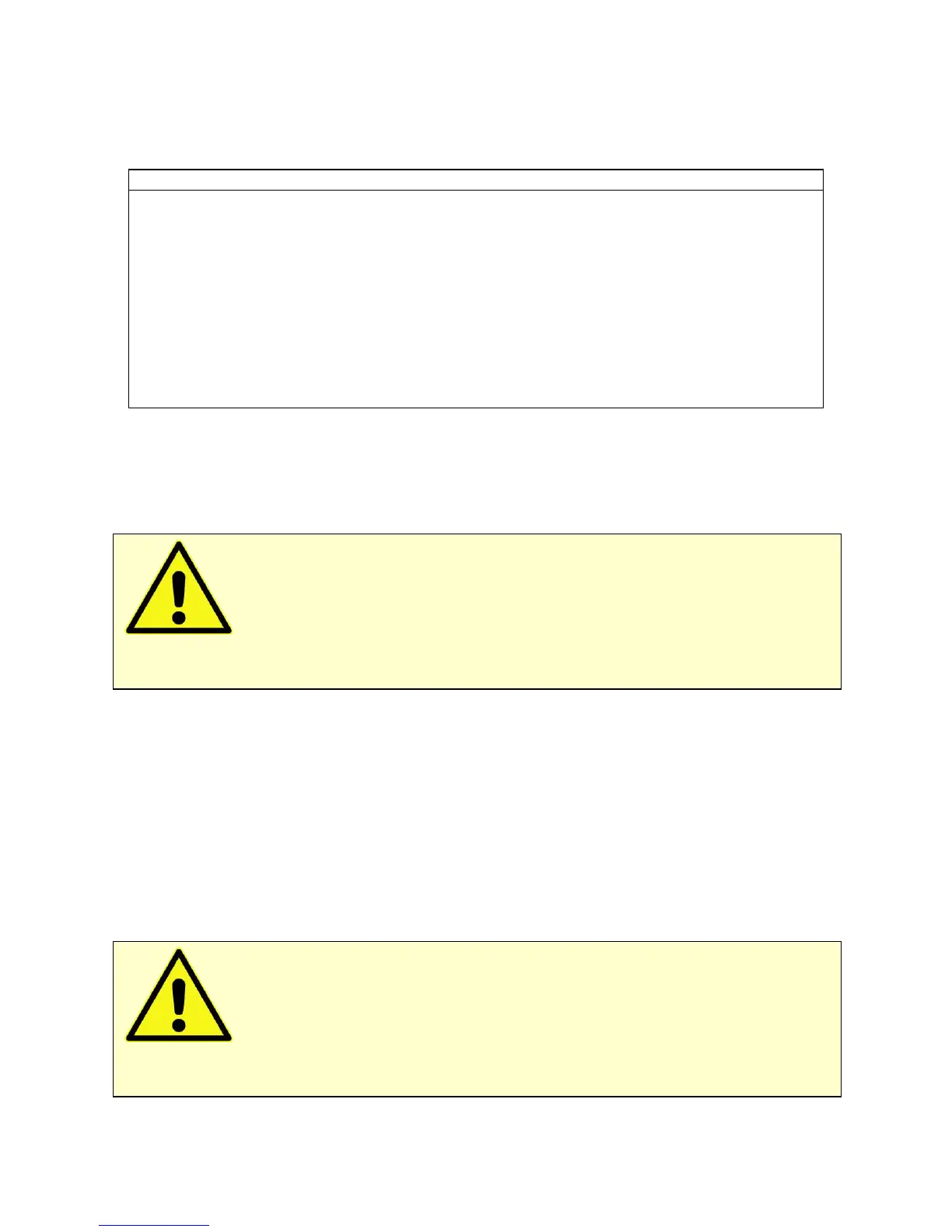
Table C-2
Monitor Connector
A high-quality floating ground. Signals are relative to this ground
Another high-quality floating ground. Signals are relative to this
ground
The Positive RTD Input. 1 mA flows between this pin and Pin 4.
The Negative RTD input. Connected to the Interface 5000’s floating
ground.
E Monitor Signal, ±6.5536 V full scale
External Signal In, ±6.5536 V full scale
I_Monitor Signal, ±3.2678 V full scale
The minus input of the differential Aux ADC Input
The positive input of the differential Aux ADC Input
I Monitor Signal
The I Monitor signal represents the output of the Interface 5000 current measurement circuit. It can be treated
as a two-wire differential signal with the negative side connected to the Interface 5000 Signal Ground. With the
exception of the filtering described below, it is the raw signal with no offset or gain applied. IE Stability
capacitors slow the response.
Scaling on this signal is 3 V for the nominal full scale current on the selected current range. Cathodic currents
cause a positive output voltage. If the software is auto-ranging the current-range selection, this signal is
discontinuous at each range change.
The I Monitor signal is filtered using an RLC circuit. It has a bandwidth of approximately 350 kHz when
connected to a high-impedance input.
E Monitor Signal
The E Monitor signal is derived from the output of the Interface 5000’s differential electrometer circuit. It can
be treated as a two-wire differential signal with the negative side connected to the Interface 5000 Signal
Ground. With the exception of the filtering described below, it is the raw voltage signal, with no offset or gain
applied. With the exception of the filtering described below, it is buffered representation of the voltage
difference between the white and blue cell cable leads.
Caution: The negative side of the E Monitor signal is connected to the Interface 5000
Floating Ground. Connection of signal to an earth-ground-referenced apparatus can compromise the
Interface 5000’s ability to float, and invalidate data collected on earth-grounded cells.
Caution: The ground side of the I Monitor signal is connected to the Interface 5000
Floating Ground. Connection signal to an earth-ground-referenced apparatus can compromise the Interface
5000’s ability to float, and invalidate data collected on earth-grounded cells.