Appendix B: Interface 5000 Cell Connectors
65
Appendix B: Interface 5000 Cell Connectors
Chapter 4 describes the connections between a cell cable and an electrochemical cell. This appendix describes
the other end of the cell cable.
Multiple pins assigned to the same signal are connected together on the Interface 5000’s Potentiostat board. If
you must connect this using a special cell cable, you need a wire connected to any one of the D-connector
pins.
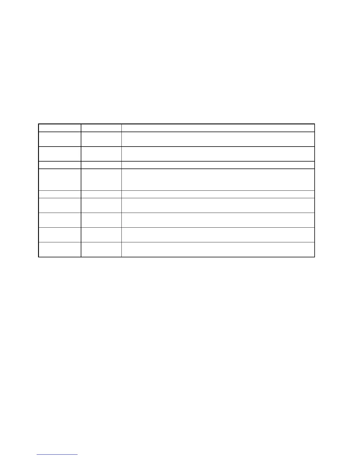
Table B-1
Current Connector
Connected to the working electrode (see Chapter 4Error! Reference source
not found.).
The shield for the working electrode. Connected to Floating Ground on D-
end of the cable. Left open at the cell end of the cell cable.
The potentiostat’s floating ground. Can be used to shield the cell if very low
currents need to be measured. Also used as a shield for the counter electrode
cable.
Connected to the counter electrode
One of four cable ID bits. Used to identify the type of cell cable attached to
the unit. Pull to a logic High through a resistor. Ground to set the bit low.
One of four cable ID bits. Used to identify the type of cell cable attached to
the unit. Pull to a logic High through a resistor. Ground to set the bit low.
One of four cable ID bits. Used to identify the type of cell cable attached to
the unit. Pull to a logic High through a resistor. Ground to set the bit low.
One of four cable ID bits. Used to identify the type of cell cable attached to
the unit. Pull to a logic High through a resistor. Ground to set the bit low.