Appendix B: Interface 5000 Cell Connectors
66
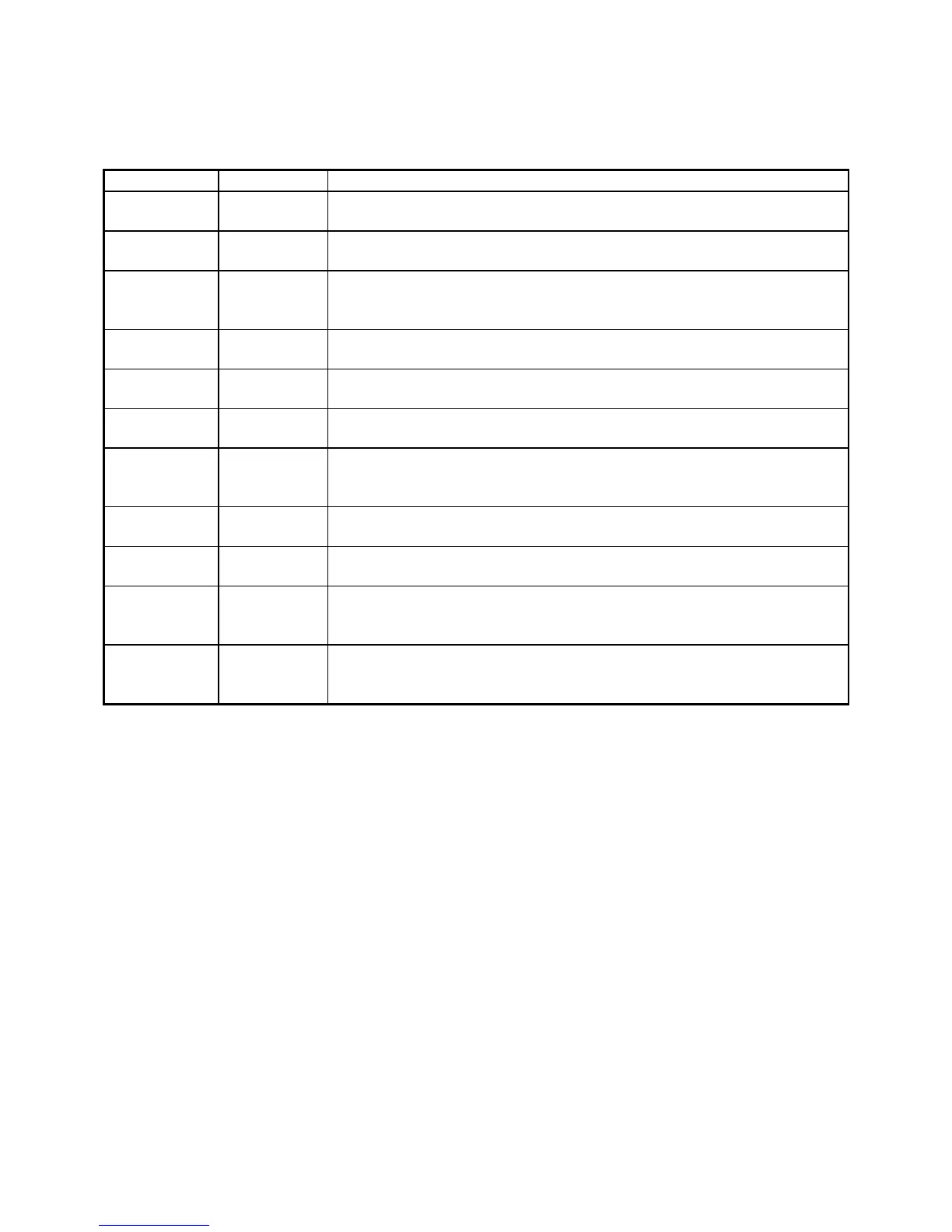
Table B-2
Sense Connector
One of four cable ID bits. Used to identify the type of cell cable attached to
the unit. Pull to a logic High through a resistor. Ground to set the bit low.
One of four cable ID bits. Used to identify the type of cell cable attached to
the unit. Pull to a logic High through a resistor. Ground to set the bit low.
The potentiostat’s floating ground. Can be used to shield the cell if very low
currents need to be measured. Also used as a shield for the counter electrode
cable.
The shield for the counter-sense electrode input. Driven to the same
potential as Pin 11. Left open at the cell end of the cell cable.
The shield for the reference electrode input. Driven to the same potential as
Pin 13. Left open at the cell end of the cell cable.
The shield for the work sense electrode input. Driven to the same potential
as Pin 8. Left open at the end of the cell cable.
Connected to the working electrode in most cases (see Chapter 5). This lead
has a 261 Ω resistor in the cell end of the cable. Custom cell cables are likely
to require a similar resistor.
One of four cable ID bits. Used to identify the type of cell cable attached to
the unit. Pull to a logic High through a resistor. Ground to set the bit low.
One of four cable ID bits. Used to identify the type of cell cable attached to
the unit. Pull to a logic High through a resistor. Ground to set the bit low.
Connected to the counter electrode in ZRA-mode and stack-mode
experiments (see Chapter 5). This lead has a 261 Ω resistor in the cell end of
the cable. Custom cell cables are likely to require a similar resistor.
Connected to the reference electrode in most cases (see Chapter 4Error!
Reference source not found.). This lead has a 261 Ω resistor in the cell end
of the cable. Custom cell cables are likely to require a similar resistor.