Panel Indicators and Connectors
45
Chapter 6: Panel Indicators and Connectors
This chapter fully describes all the front and rear panel input and output devices on the Interface 5000. USB
commands control all Interface 5000 functions, so this information is only needed for troubleshooting and
special functions.
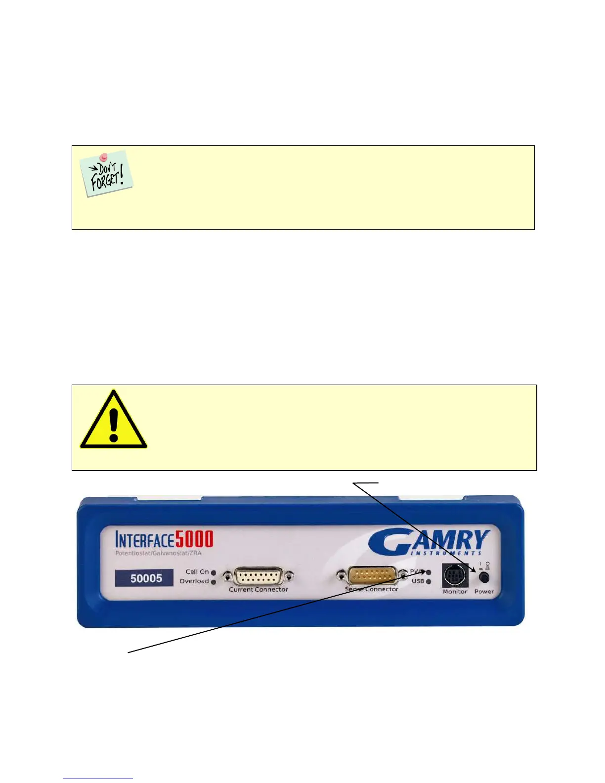
Front Panel
Power Button
The Power button is on the far right side of the Interface 5000 Front Panel. It is a push-push switch: push once
to turn the instrument on and push again to turn the instrument off. The switch’s button latches: the button is
closer to the front panel when the instrument is on than when it is off.
Normally the PWR LED illuminates when the Interface 5000 is powered on; see the PWR LED description
below.
Normally, the DC power is connected before the Power button is turned ON. However, no damage occurs if
this switch is already in the ON position when the cable is connected to Power In, or when the AC power input
is connected to the external power supply.
Power Switch
The PWR LED
The PWR LED is on the lower right of the Interface 5000 front panel. It normally glows a continuous blue when
the Interface 5000 is turned on and has passed some simple power-on tests.
Caution: Avoid touching the Power switch button during normal instrument operation.
Data are lost if the instrument is accidentally powered off during an experiment.
The Interface 5000 uses three DIN connectors for connections to external devices. The three
DIN connectors all have different numbers of pins and physical sizes, so the cables used in them cannot be
interchanged or improperly connected.