Instrument Circuitry
55
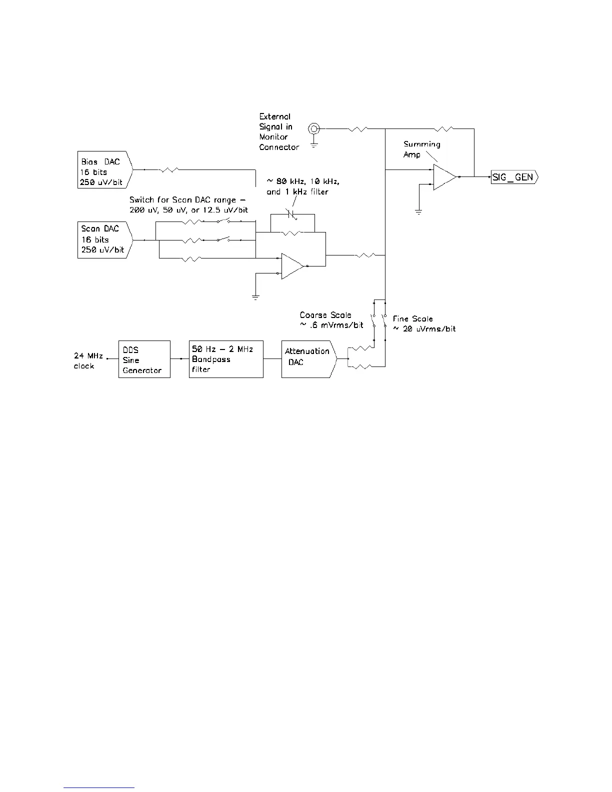
Figure 6-5
Interface 5000 Signal Generation Circuitry
Notes on Figure 6-5:
• All the resistors summing voltages into the Summing Amplifier input do not have values shown because
their values depend on scaling factors too complex for this simplified diagram.
• Calibration components are not shown.
• High-frequency sine-wave generation is done using a DDS (direct digital synthesis) IC. The DDS’s output is
filtered with both a high-pass and low-pass filter. The low-pass filter removes the steps in the DDS output.
The high-pass filter provides AC-coupling to prevent drift in the DDS’s offset entering the applied signal. In
practice, Gamry EIS software uses the DDS to apply sine waves with frequencies from 100 Hz to 1 MHz. It
uses the Scan DAC to generate sine signals at frequencies below 100 Hz.
A two-stage attenuator scales the DDS. On the coarse scale, the maximum output signal is 2.33 V
rms
(3.3
V
peak
) and the resolution is approximately 0.6 mV
rms
/bit. On the fine scale, the maximum is approximately
77 mV
rms
and the resolution is approximately 20 µV
rms
. AC-signal attenuation is handled automatically by
Gamry software.
• The Scan DAC and Bias DAC signals are filtered before they are applied to the cell. The filter bandwidths
are as shown.