Instrument Circuitry
58
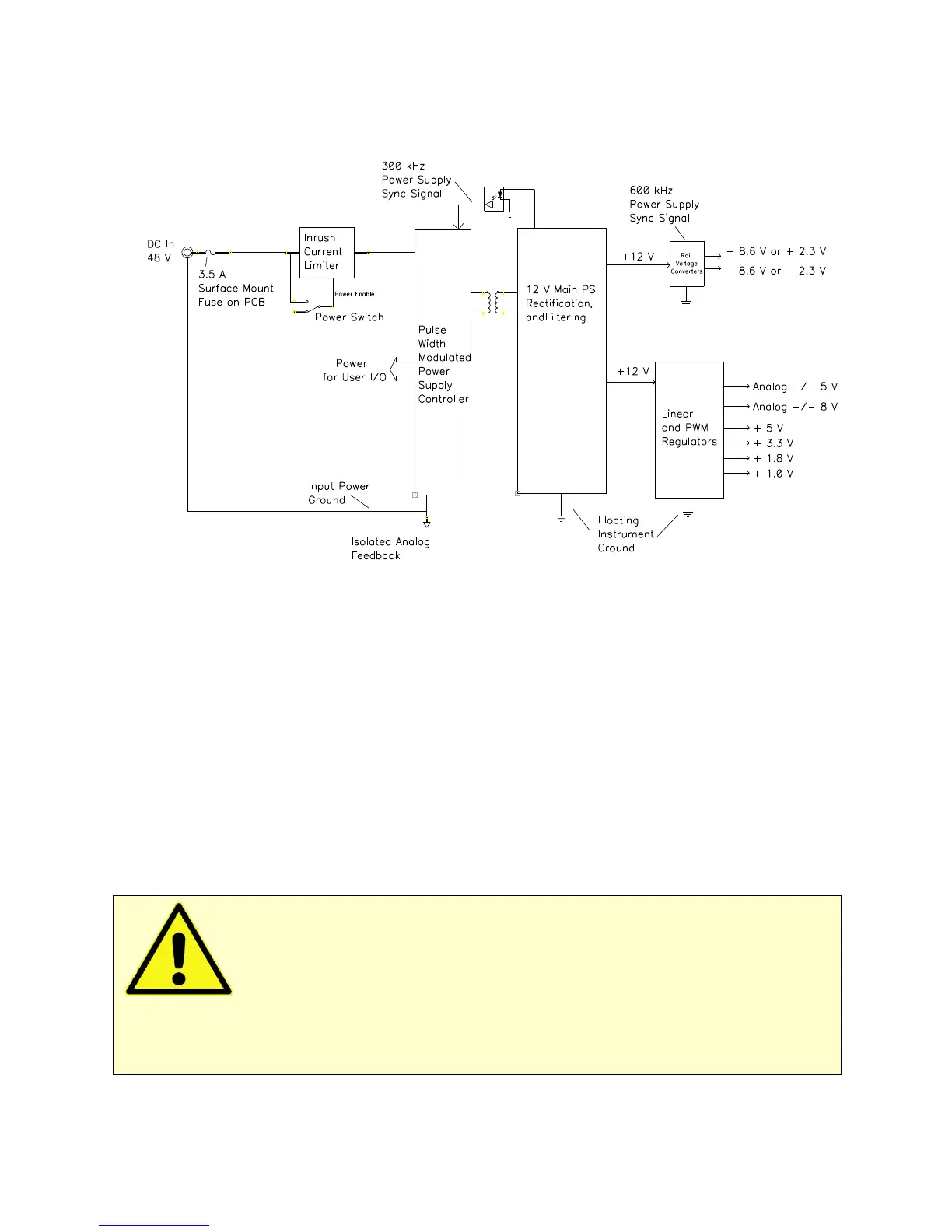
Figure 6-8
Power Conversion
Notes for Figure 6-8:
• Note the ground isolation between the input power and the Interface 5000 circuitry. The Interface 5000
chassis is connected to the Floating Instrument Ground.
Transformers and digital isolators are the only components connected between the grounds.
• Both 600 kHz and 300 kHz power-supply sync signals are derived from the same clock used to control
data-acquisition. Data points taken at an integer multiple of 1.666 µs/point are synchronized with the
power supply, minimizing the effect of power-supply noise on the data.
• The DC-DC converter powers both the floating circuitry and some earth-side circuitry, including the USB
processor and User I/O.
• Additional circuitry protects the Interface 5000 against ESD and electrical surges.
• Like most complex electronic apparatus, the Interface 5000 uses a variety of power-supply voltages.
• The incoming DC voltage must be between 46 and 50 V. With inputs below 46 V, the PWM may be
unable to regulate the supply. Above 50 V, the PWM may not start-up.
Caution: Do not use a DC power source other than the AC adapter model provided with
your Interface 5000 or a Gamry-supplied alternative. Other power sources may void the performance
and/or safety characteristics of the Interface 5000.
Power input voltages less than 40 V or greater than 52 V can damage the Interface 5000’s power supply.