13-10-614 Page 10
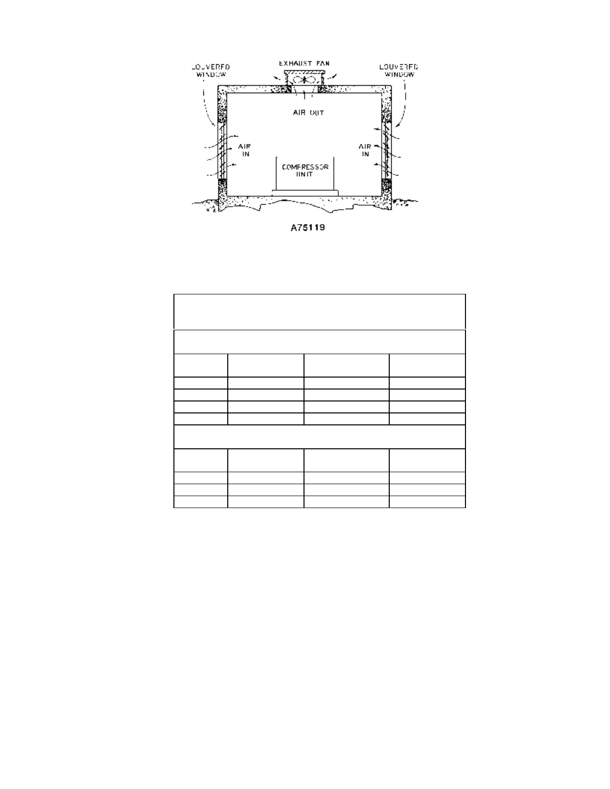
Figure 2-1 – TYPICAL COMPRESSOR ROOM
Minimum Air Flow * for Compression
and Cooling
DOMESTIC (CFM)
HP Air-Cooled
Package
Air-Cooled
Module
Water-Cooled
Package
200 28,500 20,500 8,000
250 35,900 26,000 9,900
300 37,900 26,000 11,900
INTERNATIONAL (M
3
/MIN)
KW Air-Cooled
Package
Air-Cooled
Module
Water-Cooled
Package
150 806 580 226
186 1,016 736 280
224 1,072 736 337
* 80° F (27° C) Inlet Air
Figure 2-2 – AIR FLOW CHART
Air-Cooled Units - A combination oil/aftercooler is supplied as standard equipment on all air-cooled
units. The air-cooled unit with the standard enclosure requires sufficient flow, Figure 2-2, for the
compressor oil/aftercooling system and for electric motor cooling. Air is drawn into the unit at the motor
side of the enclosure and is exhausted at the oil cooler side. Do not block the air flow to and from the
unit. Allow three and one-half (3-1/2) feet (1.1 m) to the nearest obstruction on the starter end and control
box end of the unit. Allow three (3) feet (.9 m) to the nearest obstruction above and on other sides of unit.
For continuous efficiency, oil cooler cores must be periodically cleaned with either vacuum or compressed
air. If wet cleaning is required, shield motor and spray on a mild soap solution and flush with clean water.
Water-Cooled Units - The water-cooled unit with the standard enclosure requires sufficient air flow,
Figure 2-2, page 10, for electric motor cooling. Air is drawn into the unit at the top of the enclosure and is
exhausted at the motor side. Do not block air flow to and from unit. Allow three and one-half (3-1/2) feet