13-10-614 Page 50
5. To install a new oil filter, rotate the threaded portion of the filter head to align the channel.
6. Align the tabs on the filter element with the channels in the filter head and snap the element into
the filter head.
7. Press the filter assembly into the filterstat assembly. Using a 1” socket tighten down the oil filter,
until the o-ring seals. Do not overtighten.
8. Run the unit and check for leaks.
COMPRESSOR OIL COOLER - RADIATOR TYPE (Figure 1-5, page 5 and Figure 1-6, page 5) - The oil
cooler motor and fan is mounted on the oil cooler module; air is exhausted through the oil cooler and
away from the unit. Do not obstruct air flow to and from the oil cooler. Allow a minimum of three (3) feet
clearance around the cooler. Keep both faces of cooler core clean for efficient cooling of compressor oil.
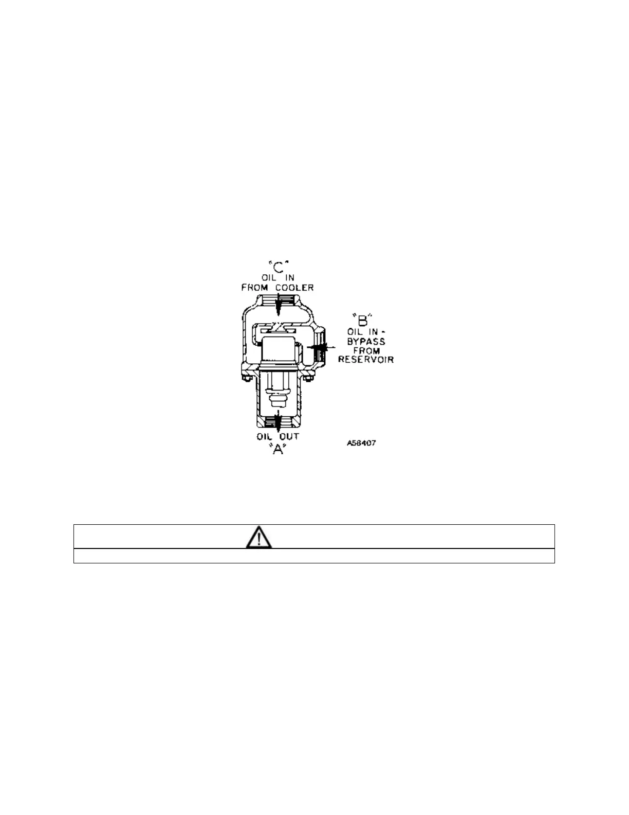
Figure 5-9 – THERMOSTATIC MIXING VALVE ELEMENT
WARNING
Ducting will be required on air cooled quiet enclosed machines.
THERMAL CONTROL (THERMOSTATIC MIXING) VALVE is installed in system as shown in Figure 5-3,
page 40. This valve is used to control temperature of the oil in both air-cooled radiator and water-cooled
heat exchanger type oil cooler systems. On start-up with unit cold, element is open to bypass, allowing
oil to pass directly from the reservoir to compressor during warm-up. As oil warms, element gradually
closes to the bypass allowing more of the oil from the cooler to mix with oil from the bypass.
After the unit is warmed up, the mixing valve maintains oil injection temperature into the compressor at a
minimum of 150° F (66° C). This system provides proper compressor warm-up and helps prevent
moisture contamination of oil.
To check the element, heat in oil -- it should be fully extended at 150° F (66° C). If the unit shuts down
due to high air discharge temperature, it may be that one or both thermostatic mixing valve elements
(Figure 5-3, page 40) are stuck open. Remove the mixing valve and clean all parts thoroughly when
flushing the oil system.