13-10-614 Page 28
COMPRESSOR CAPACITY CONTROL
The capacity of the compressor is controlled by the action of the Turn Valve and the Compressor Inlet
Valve.
The turn valve controls compressor delivery to match demands of 40% to 100% of the compressor’s
maximum capacity. The inlet valve throttles to control compressor delivery to match demands of 0% to
40% of the compressors maximum capacity.
Example with normal setting of 100 PSIG:
Compressor Delivery Inlet Valve Position Turn Valve Position
Discharge Manifold
Pressure (psi)
Full Capacity Open Closed 100
70% Capacity Open 50% Open 100
40% Capacity Open Full Open 100
30% Capacity Closing Full Open 103
20% Capacity Closing Full Open 103
0% Capacity Closed Full Open 103
Turn Valve - The turn valve is a helical valve which, when rotated, opens and closes a series of ports
cast into the compressor cylinder. When these ports are open, they direct some of the air which would
otherwise be compressed back to the inlet, reducing both capacity and power consumption.
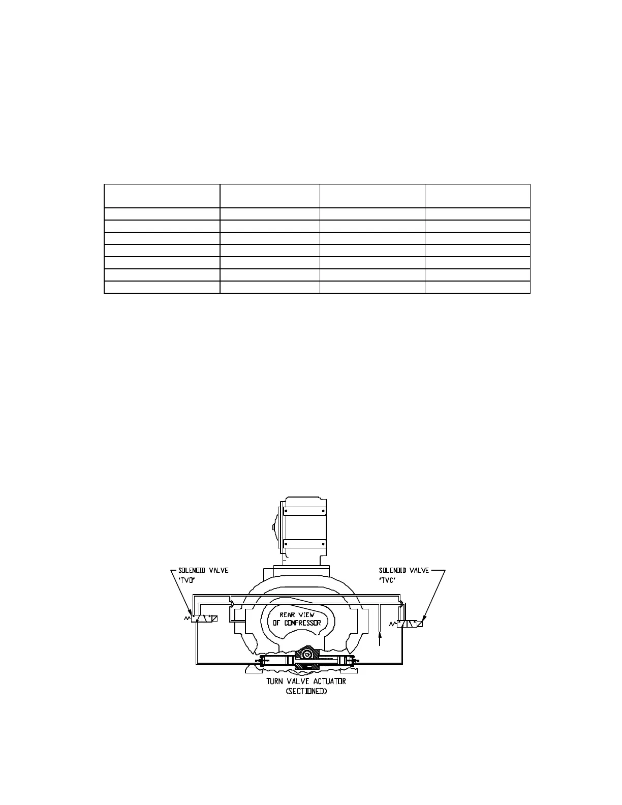
Turn Valve Actuator (Figure 4-6) - The turn valve actuator is a rotary rack and pinion device which
positions the turn valve according to system demand. Filtered oil from the reservoir is directed to the
outboard ends of the two actuating cylinders to move the rack and rotate the valve. Located on the end
of the cylinders are adjusting screws which limit the travel of the actuator. When looking at the rear of the
compressor, the adjusting screw on the right on the compressor adjusts the fully closed (full load) position
of the valve. The full load position of the actuator may be checked by removing the adjusting screw at the
unloaded end of the actuator (left side of the compressor) and using a rod to push the pistons to the full
load position. The rod must be clean and free of burrs and scale. Take care not to scrape the cylinder
walls when moving the pistons.
Figure 4-6 – TURN VALVE ACTUATOR (SECTIONED)
(Ref. Drawing)