Garmin G5 User's Manual
190-02072-00 Rev. B 19
Installation Manual
Installation Manual Pilot's Guide Index
1.3.6 MOUNTING INSTRUCTIONS
Refer to Section 1.3.7 for outline and installation drawings.
NOTE:
In addition to the mounting requirements listed in Section
1.3.4.1, it is critical that the G5 is installed perpendicular to the aircraft's
longitudinal axis (display bezel parallel to the wing spar) and as close to
level in the roll axis as possible. Small roll offsets, and pitch offsets up
to 30°, can be corrected for during calibration.
1.3.6.1 PANEL CUTOUT TEMPLATE
The G5 Mounting Ring (115-02251-03) or Figure 1-13 can be used as a template
when marking the panel for cutout. See Figure 1-12 for complete cutout dimensions
(the dimensions on Figure 1-12 are to verify the accuracy of the printout only).
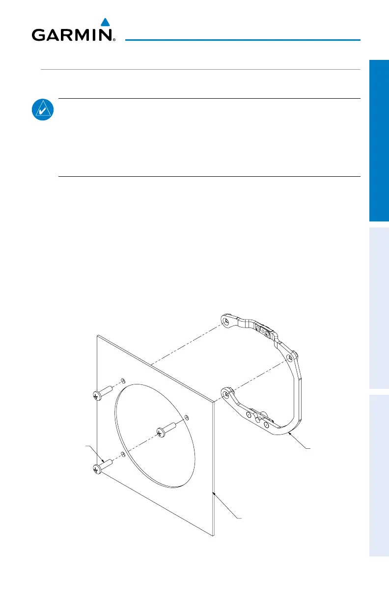
1.3.6.2 MOUNTING RING INSTALLATION
Secure the mounting ring to the aircraft panel using the supplied #6-32 pan head
Phillips mounting screws. Evenly torque the mounting screws to 10-12 in-lbs.
115-02251-03
AIRCRAFT PANEL
MOUNTING SCREW,
211-60207-12
3 PLACES
Figure 1-6 G5 Mounting Ring