10 GHP12InstallationInstructions
4. Connect the GHP 12 rudder feedback cable (not included) to your
drive unit, based on the wire colors and functions dened below.
Red Feedback positive (+)
Black Feedback negative (-)
Yellow Feedback wiper
If necessary, extend the appropriate wire with 22 AWG (.33 mm
2
)
wire.
5. If necessary, use the installation instructions provided with the drive
unit to install it on your boat.
The GHP 12 drive unit power cable is shipped with a 40 A, blade-type
fuse. The included fuse must not be used if it is not the appropriate fuse
for your drive unit.
1. Consult the manufacturer of your drive unit to determine the correct
fuse type.
2. Select an option:
• If the 40 A fuse is appropriate, install it in the fuse holder.
• If your drive unit requires a different fuse, install the correct fuse
for your drive unit.
To install the ECU, you must mount it to your boat, connect it to the
drive unit, and prepare the battery wiring.
Before you can install the ECU, you must select a mounting location
and determine the correct mounting hardware (page 5).
1. Cut out the mounting template provided on page 29.
2. Tape the template to the mounting location.
3. Drill pilot holes at the four mounting locations.
4. Use screws to mount the ECU.
Connect the two cables from the drive unit to the connectors marked
DRIVE and FEEDBACK on the ECU.
The connectors are keyed and color coded to the appropriate ttings
on the wires.
Notice
Do not remove the in-line fuse holder from the battery cable when
connecting to the battery. If you remove the in-line fuse holder, you will
void the GHP 12 warranty and possibly damage the GHP 12 autopilot
system.
You should connect the ECU power cable directly to the boat battery
if possible. Although it is not recommended, if you connect the power
cable to a terminal block or other source, connect it through a 40 A fuse.
If you plan to route the ECU through a breaker or a switch near the
helm, consider using an appropriately sized relay and control wire
instead of extending the ECU power cable.
1. Route the connector-terminated end of the ECU power cable to the
ECU, but do not connect it to the ECU.
2. Route the bare-wire end of the ECU power cable to the boat battery.
If the wire is not long enough, it can be extended. Consult the table
to determine the correct wire gauge for an extended run.
10 ft. (3 m) 12 AWG (3.31 mm
2
)
15 ft. (4.5 m) 10 AWG (5.26 mm
2
)
20 ft. (6 m) 10 AWG (5.26 mm
2
)
25 ft. (7.5 m) 8 AWG (8.36 mm
2
)
3. Connect the black wire (-) to the negative (-) terminal of the battery.
4. Connect the red wire (+) to the positive (+) terminal of the battery.
5. Do not connect the ECU power cable to the ECU.
Connect the power cable to the ECU only after you install all of
the other GHP 12 components.
To install the CCU, you must mount it to your boat, connect it to the
ECU, connect it to a NMEA 2000 network, and connect it to the alarm
and to the yellow CCU signal wire on the GHC 10.
Before you can mount the CCU, you must select a location and
determine the correct mounting hardware (page 5).
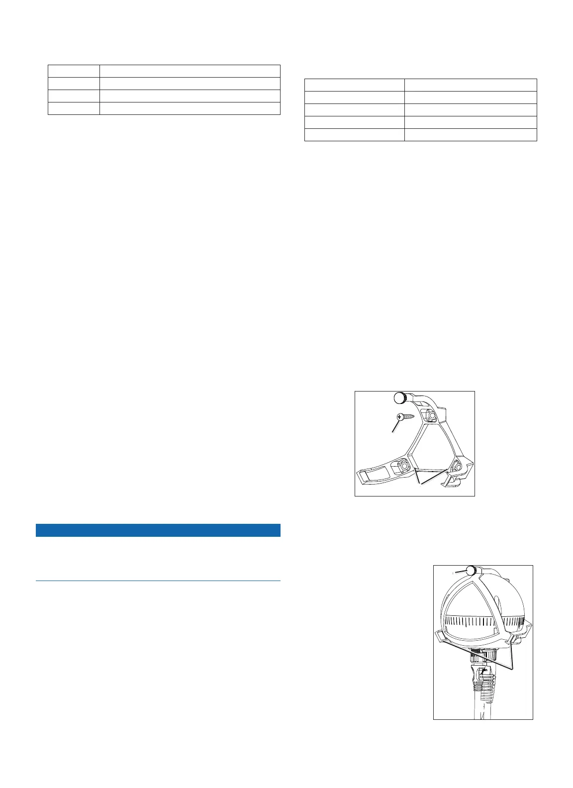
The CCU bracket has two portions, the mounting portion and the
securing portion.
1. Cut out the mounting template provided on page 29.
2. Tape the template to the mounting location.
If you are installing the CCU on a vertical surface, install the
mounting portion of the bracket with an opening
➊
at the bottom.
➊
➋
3. Drill pilot holes at the three mounting locations.
4. Use screws
➋
to secure the mounting portion of the CCU bracket.
1. Connect the CCU/ECU interconnect cable and the NMEA 2000
drop cable to the CCU.
2. Place the CCU in the mounting
portion of the CCU bracket with
the wires hanging straight down
➊
.
3. Place the securing portion of the
bracket over the ball and snap
it it into the mounting portion
of the bracket, starting with the
two arms
➋
that do not have the
thumbscrew
➌
.
➊
➋
➌

 Loading...