8 GHP12InstallationInstructions
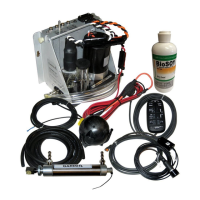
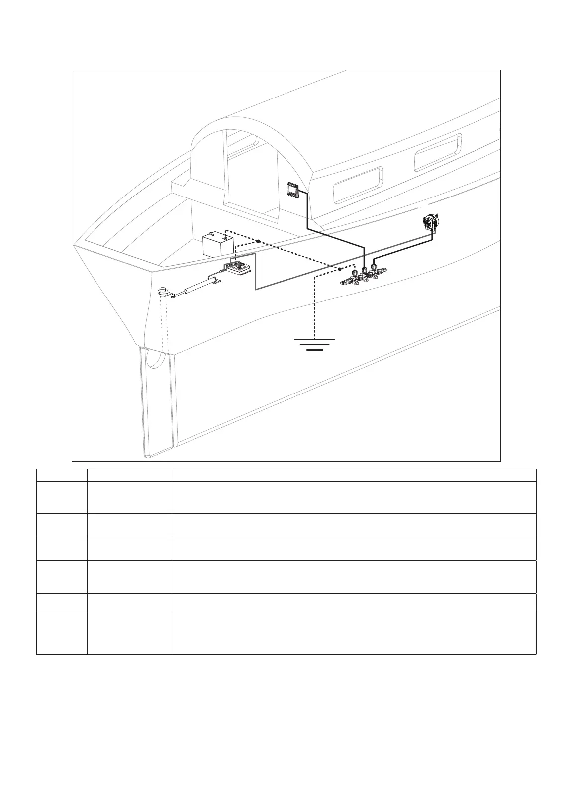
Refer to this diagram for component-layout reference only. Follow the detailed installation instructions for each component (pages 9–14).
➊
➋
➌
➍
➎
➏
➊
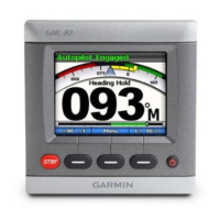
GHC 10 In order for the autopilot to turn on, the yellow wire from the GHC 10 data cable must be connected to the
yellow wire from the CCU/ECU Interconnect cable, and the black wire from the GHC 10 data cable must
be connected to the same ground as the ECU (page 12).
➋
12-24 Vdc battery The ECU can connect to a 12–24 Vdc power source.
The NMEA 2000 power cable must be connected to a 9–16 Vdc power source.
➌
CCU
The CCU must be installed in the front half of the boat,
no higher than 10 ft. (3 m) above the waterline
➍
Drive unit
If you are using the GHP 12 with a non-Garmin drive unit, you must purchase a GHP 12 drive unit cable
(page 9).
➎
ECU The ECU can either be connected to a 12 or a 24 Vdc battery.
➏
NMEA 2000 network The GHC 10 and the CCU must be connected to the NMEA 2000 network using the included T-connectors
(page 12).
If there is not an existing NMEA 2000 network on your boat, you can build one using the supplied cables
and connectors (page 13).

 Loading...