GHP12InstallationInstructions 21
6. When the drive-unit speed is tuned correctly, select Done.
The error tolerance of the drive unit determines how much error the
autopilot allows before adjusting the drive unit.
If you set the error tolerance too low, the drive unit will react to the
slightest course deviation. This causes the drive to work harder and may
drain your battery at a faster-than-normal speed.
If you set the error tolerance too high, the drive unit will not react until
your course is off a signicant distance. This causes a less reliable
heading hold, and can result in unnecessarily large course corrections.
1. From the Heading screen, select Menu > Setup > Dealer Autopilot
Conguration > Steering System Setup > Drive Unit Type.
2. Select Other or Solenoid, according to what you set in the dockside
wizard.
3. Select Advanced Tuning > Tune Error Tolerance.
4. Center the rudder position, let go of the rudder control, and select
Begin.
5. Select Tune.
The rudder position moves from +5° to -5° each time you select
Tune, and the drive unit steers and holds the rudder accordingly.
6. After the drive unit stops, observe the rudder error and power usage
elds for 30 seconds.
• If the power usage eld uctuates, then your error tolerance is
set too low.
• If the power usage eld stays at 0%, but the rudder error eld
shows and unacceptable degree of error (1% or more), then your
error tolerance is set too high.
TIP: An ideal error tolerance conguration holds the rudder at
an acceptable degree of error (.5% or so) without unnecessarily
adjusting the drive unit and wasting power (0% for 30 seconds
or more).
7. If necessary, select Adjust.
8. Select an option:
• Decrease the value if the error tolerance is too high, and repeat
steps 3–5.
• Increase the value if the error tolerance is set too low, and repeat
steps 3–5.
9. When the drive-unit error tolerance is tuned correctly, select Back.
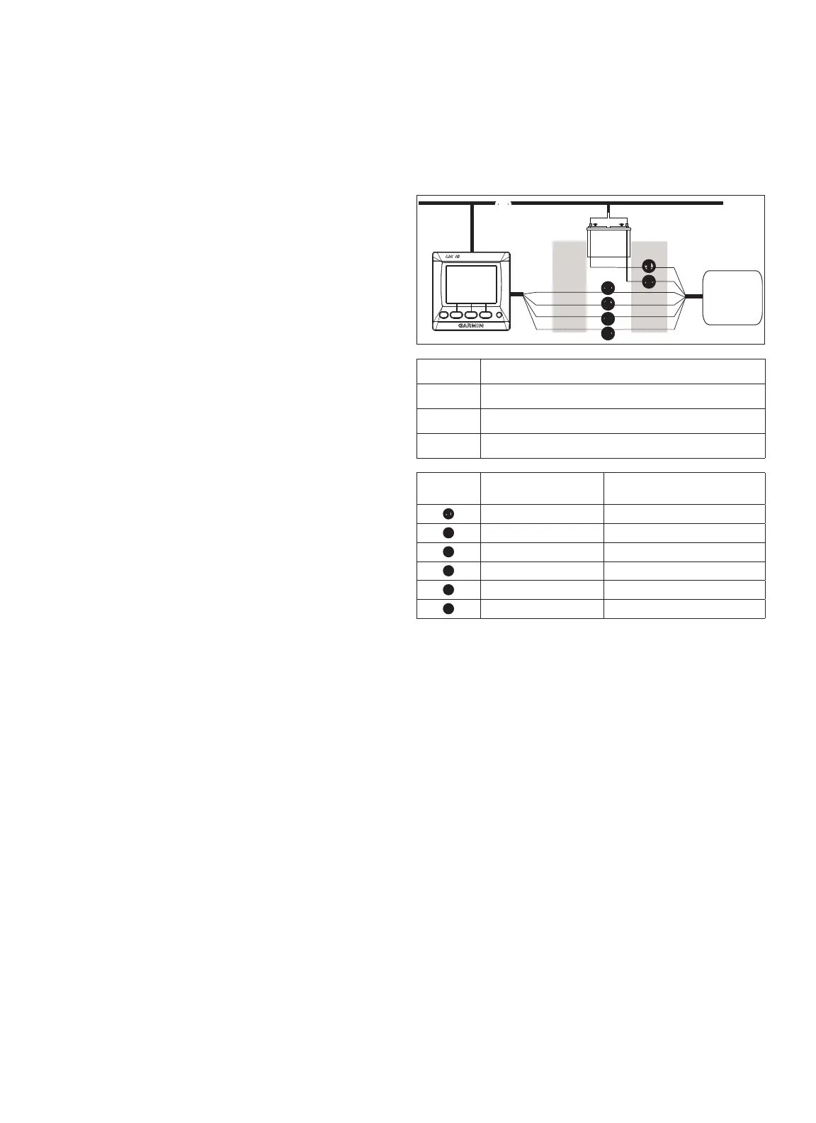
The following three wiring diagrams are examples of different
situations you may encounter when wiring your NMEA 0183 device to
the GHC 10.
>
>
>
>
>
>
>
>
+
-
➊
➌
➋
➊
➍
➎
➏
➋
➍
➌
➊
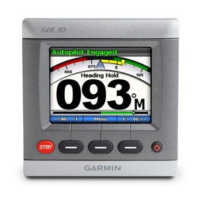
GHC 10
➋
NMEA 2000 network (provides power to the GHC 10)
➌
12 Vdc power source
➍
NMEA 0183-compatible device
➊
N/A Power
➋
N/A NMEA 0183 ground
➌
Blue - Tx/A (+) Rx/A (+)
➍
White - Tx/B (-) Rx/B (-)
➎
Brown - Rx/A (+) Tx/A (+)
➏
Green - Rx/B (-) Tx/B (-)
NOTE: When connecting NMEA 0183 devices with two transmitting
and two receiving lines, it is not necessary for the NMEA 2000 bus and
the NMEA 0183 device to connect to a common ground.

 Loading...