14 GHP12InstallationInstructions
To use advanced features of the GHP 12, optional NMEA
2000-compatible or NMEA 0183-compatible devices, such as a wind
sensor, a water-speed sensor, or a GPS device, can be connected to the
NMEA 2000 network or to the GHC 10 through NMEA 0183.
1. Add an additional T-connector (not included) to the NMEA 2000
network.
2. Connect the device to the T-connector by following the instructions
provided with the device.
• To identify the Transfer (Tx) A(+) and B(-) wires for your NMEA
0183-compatible device, consult the installation instructions for
your device.
• When connecting NMEA 0183 devices with two transmitting and
two receiving lines, it is not necessary for the NMEA 2000 bus and
the NMEA 0183 device to connect to a common ground.
• When connecting a NMEA 0183 device with only one transmitting
(Tx) line or with only one receiving (Rx) line, the NMEA 2000
bus and the NMEA 0183 device must be connected to a common
ground.
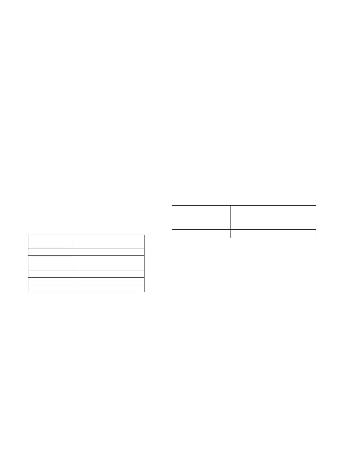
1. Determine the NMEA 0183 wiring assignments of your NMEA
0183-compatible device.
2. Refer to the table below to wire your NMEA 0183-compatible
device to the GHC 10.
Black CCU signal ground
Yellow CCU signal
Blue Tx/A (+)
White Tx/B (-)
Brown Rx/A (+)
Green Rx/B (-)
Three examples of various wiring situations are provided in the
appendix (page 21).
3. If necessary, use 22 AWG (.33 mm
2
) twisted-pair wire for extended
runs of wire.
4. Solder and cover all bare-wire connections.
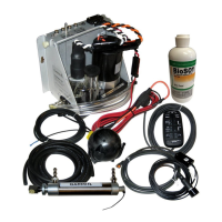
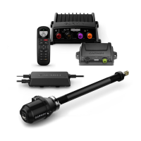
The Shadow Drive (optional accessory) is a sensor you install in the
hydraulic steering lines of your boat. The Shadow Drive can only be
used on a boat with a hydraulic steering system.
To install the Shadow Drive, connect it to the hydraulic steering line of
your boat and connect it to the CCU/ECU interconnect cable.
Before you can install the Shadow Drive, you must select a location at
which to connect the Shadow Drive to the hydraulic steering of your
boat, after you have read and followed the mounting and connection
considerations (page 6).
Use the connectors included with the Shadow Drive to install the
Shadow Drive in the hydraulic line.
When connecting the Shadow Drive to the hydraulic system, follow the
important considerations (page 6).
To connect the Shadow Drive, connect it to the CCU/ECU interconnect
cable.
1. Route the bare-wire end of the CCU/ECU interconnect cable to the
Shadow Drive.
If the cable is not long enough, extend the appropriate wires with 28
AWG wire.
2. Connect the cables, based on the table below.
Red (+) Brown (+)
Black (-) Black (-)
3. Solder and cover all bare-wire connections.

 Loading...