GHP12InstallationInstructions 9
After you have planned the GHP 12 installation on your boat and
satised all of the mounting and wiring considerations for your
particular installation, you can begin mounting and connecting the
components.
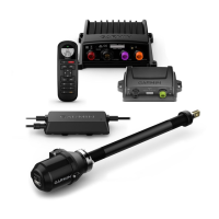
The drive unit drives the rudder and is sold separately from the GHP 12.
When you purchase a drive unit from Garmin, it will have the correct
cables and connectors.
If a drive unit is installed on your boat already, you can purchase GHP
12 drive unit cables (not included) to adapt your drive unit for use with
the GHP 12.
Use the installation instructions provided with the drive unit to
install it on your boat.
In order to use a non-garmin drive unit with the GHP 12, you must
install both the GHP 12 drive unit power cable and the GHP 12 rudder
feedback cable. Both cables are sold separately.
These instructions do not apply to a solenoid-type drive unit. To prepare
a solenoid-type drive unit, see page 9.
1. If your drive unit has cables connected, disconnect the cables.
2. Consult the documentation provided by the manufacturer of your
drive unit to identify the connections on your drive unit.
3. Connect the GHP 12 drive unit power cable (not included) to your
drive unit, based on the wire colors and functions dened below.
Red Drive unit positive
Black Drive unit negative
Blue Clutch power (cut and tape this wire if your drive unit
has no clutch)
White Clutch ground (cut and tape this wire if your drive
unit has no clutch)
The GHP 12 drive unit power cable cannot be extended.
4. Connect the GHP 12 rudder feedback cable (not included) to your
drive unit, based on the wire colors and functions dened below.
Red Feedback positive (+)
Black Feedback negative (-)
Yellow Feedback wiper
If necessary, extend the appropriate wire with 22 AWG (.33 mm
2
)
wire.
5. If necessary, use the installation instructions provided with the drive
unit to install it on your boat.
In order to use a solenoid drive unit with the GHP 12, you must install
both the GHP 12 drive unit power cable and the GHP 12 rudder
feedback cable. Both cables are sold separately.
These instructions apply only to solenoid-type drive units. To prepare a
non-solenoid drive unit, see page 9.
1. If your solenoid drive unit has cables connected, disconnect the
cables.
2. Consult the documentation provided by the manufacturer of your
solenoid drive unit to identify the connections on your drive unit.
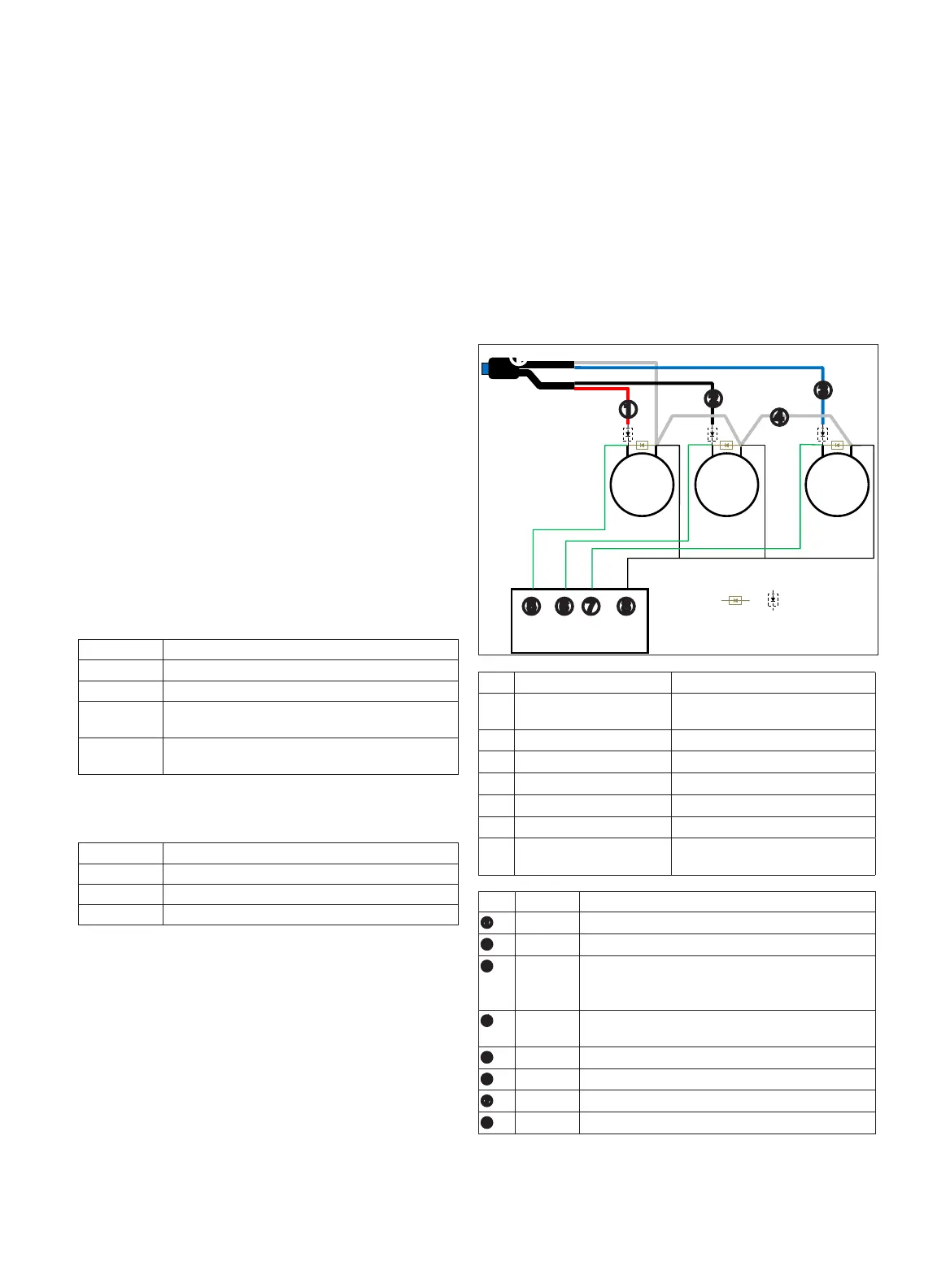
3. Connect the GHP 12 drive unit power cable (not included) to your
solenoid drive unit, based on the diagram and tables below.
The GHP 12 drive unit power cable cannot be extended.
+ -
+ -
+ -
➊
➋ ➌ ➍
➎
➏ ➐
➊
➋
➌
➍
➎ ➏ ➑➐
➊
GHP 12 Drive Unit Power
Cable
Sold separately.
➋
Starboard solenoid
➌
Port solenoid
➍
Bypass solenoid May not be present in all systems.
➎
Auxiliary steering system May not be present in all systems.
➏
Flyback diode Required for all installations.
➐
Blocking diode Required if an auxiliary steering
system is present.
➊
Red Connect to starboard solenoid positive (+).
➋
Black Connect to port solenoid positive (+)
➌
Blue Connect to bypass solenoid positive (+).
Cut and tape this wire if no bypass solenoid is
present
➍
White Connect to starboard, port, and bypass solenoid
common (-).
➎
N/A Auxiliary steering starboard positive (+) (if present).
➏
N/A Auxiliary steering port positive (+) (if present).
➐
N/A Auxiliary steering bypass positive (+) (if present).
➑
N/A Auxiliary steering common (-) (if present).

 Loading...