GHP12InstallationInstructions 7
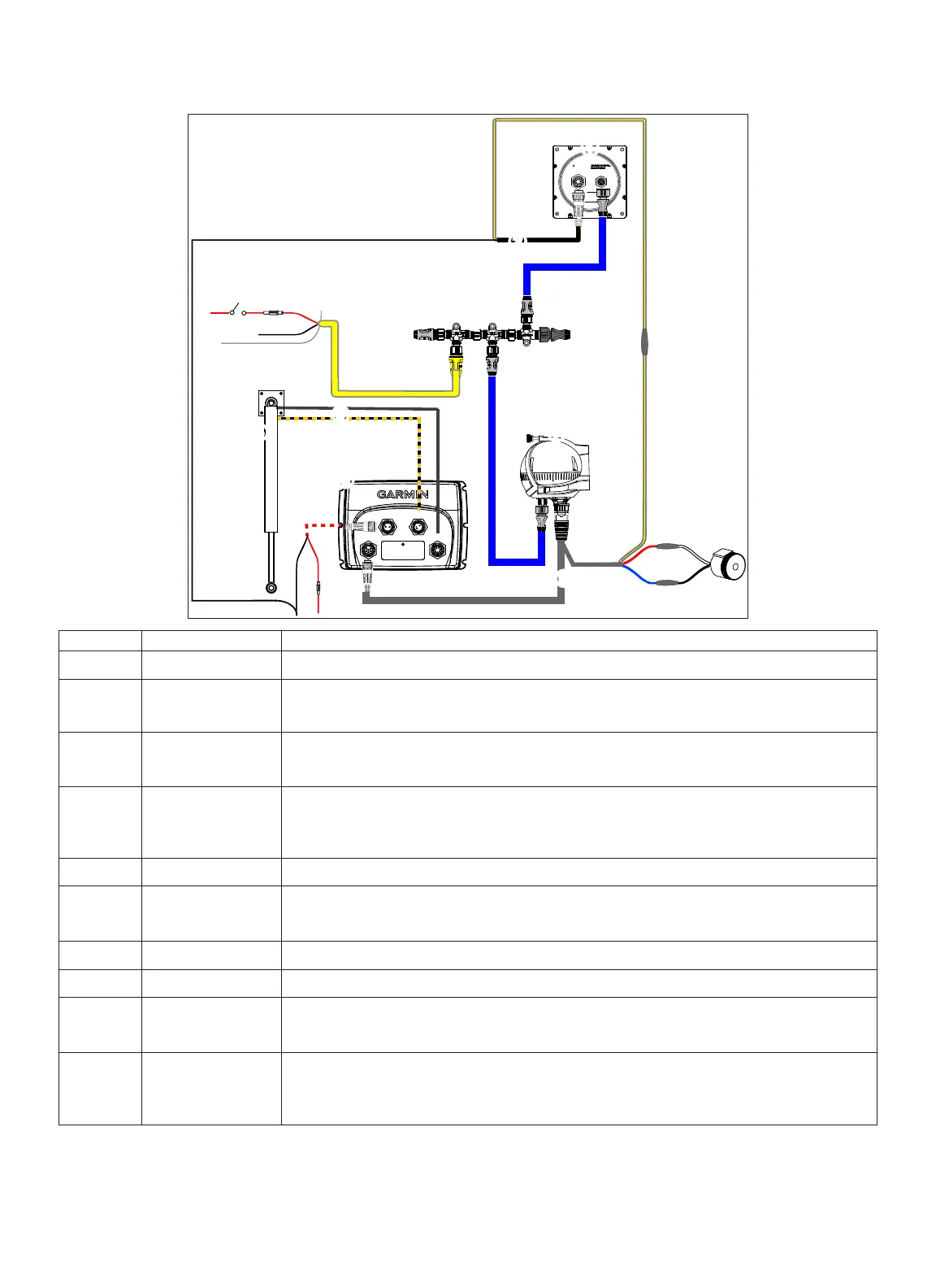
Refer to this diagram for component-interconnection reference only. Follow the detailed installation instructions for each component (pages 9–14).
FEEDBACK
CCU
POWER
DRIVE
➊
➋
➌
➍
➎
➏
➒
➓
➑
➐
➊
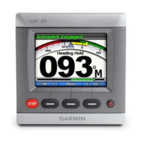
GHC 10
➋
GHC 10 data cable In order for the autopilot to turn on, the yellow wire from this cable must be connected to the yellow wire
from the CCU/ECU Interconnect cable, and the black wire from this cable must be connected to the same
ground as the ECU (page 12).
➌
NMEA 2000 power
cable
This cable should only be installed if you are building a NMEA 2000 network. Do not install this cable if
there is an existing NMEA 2000 network on your boat (page 13).
The NMEA 2000 power cable must be connected to a 9–16 Vdc power source.
➍
NMEA 2000 network The GHC 10 and the CCU must be connected to the NMEA 2000 network using the included T-connectors
(page 12).
If there is not an existing NMEA 2000 network on your boat, you can build one using the supplied cables
and connectors (page 13).
➎
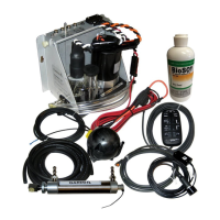
Drive unit The drive unit must be installed by an experienced professional (page 9).
➏
Drive unit power and
feedback cables
If you are using the GHP 12 with a non-Garmin drive unit, you must purchase a GHP 12 drive unit power
cable and a GHP 12 rudder feedback cable (page 9).
➐
CCU Mount the CCU with the cables pointing straight down (page 10).
➑
ECU The ECU can be mounted in any orientation.
➒
ECU power cable The ECU can be connected to a 12–24 Vdc power source. To extend this cable, use the correct wire gauge
(page 10).
The black wire from the GHC 10 data cable must connect to the same ground as this cable (page 12).
➓
CCU/ECU interconnect
cable
In order for the autopilot to turn on, the yellow wire from this cable must be connected to the yellow wire
from the GHC 10 data cable.
To extend this cable to reach the ECU, purchase the necessary extensions (page 4).
The red and blue wires from this cable connect to the alarm (page 11).

 Loading...