EasyManua.ls Logo

GE Grid Solutions MDS Master Station - COM2 Interface

GE Grid Solutions MDS Master Station
137 pages
Print Icon
To Next Page IconTo Next Page
To Previous Page IconTo Previous Page
Loading...
MDS 05-6399A01, Rev. F MDS™ Master Station 99
Table 6-6. COM1 Pin Descriptions
Pin
Number
Radio Input/
Output
Pin Description
7
OUT
CTS (Clear-to-Send)Can be used for flow control or
as an output to key another connected radio.
8
IN
RTS (Request-to-Send)Can be used for flow control
or to key the transmitter.
COM2 Interface
The COM2 port supports the RS-232 or RS-485 serial data format at serial data rates of 300,
1200, 2400, 4800, 9600, 19200, 38400, 57600, and 115200 bps (asynchronous only).
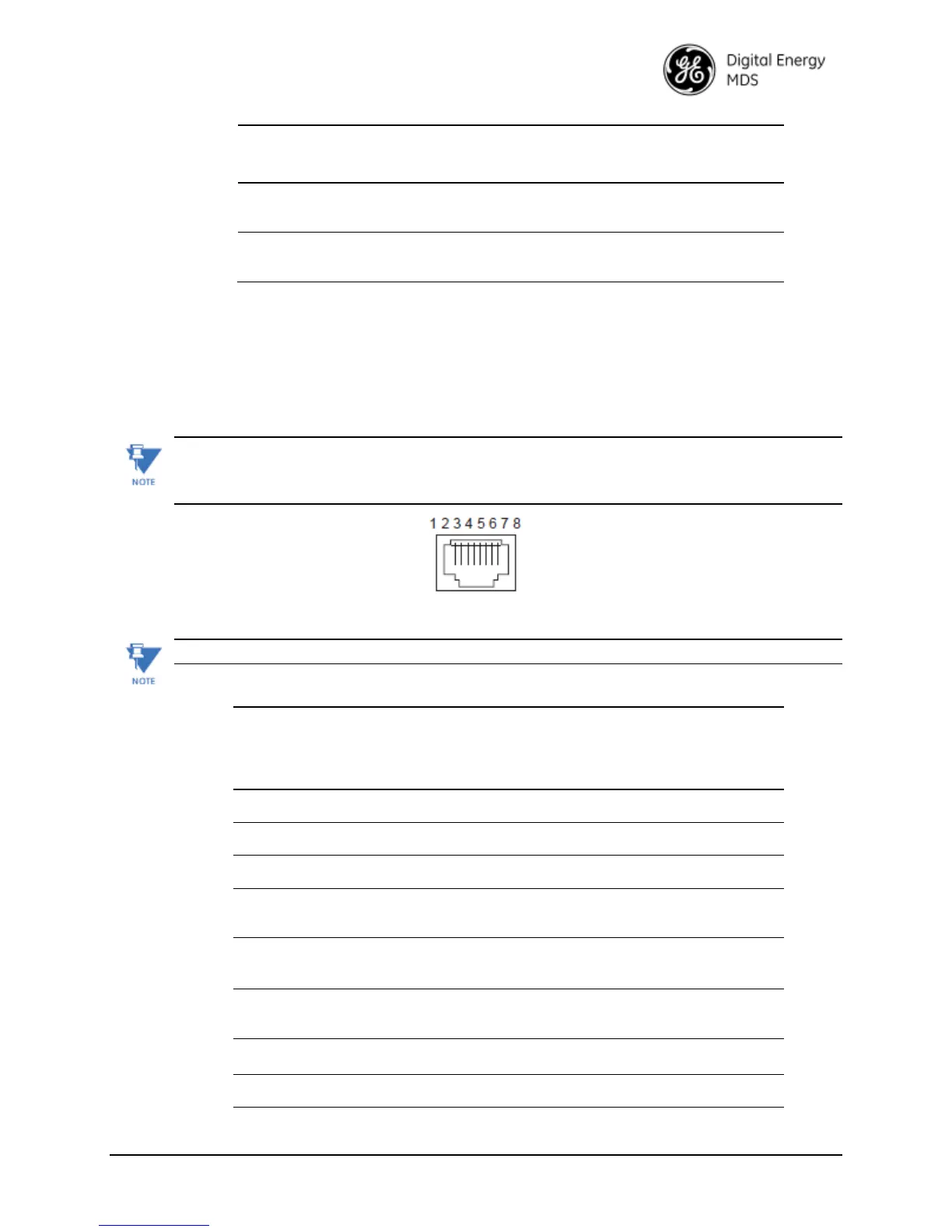
Pin DescriptionsRS-232 and RS-485
Pin descriptions for the COM2 data port in RS-232 mode and RS-485 modes are provided below.
In addition to RS-485 mode, the radio is capable of operating in RS-422 mode.
Configure the port for RS-485 but follow the RS-422 wiring arrangements shown in
below under COM2 RS-485 and RS-422 Wiring Arrangement.
Figure 6-6. COM2 Connector (RJ-45)
(As viewed from outside the radio)
COM2 is hard-wired as a DCE device.
Table 6-7. COM2 Pin DescriptionsRadio in RS-232 Mode
Pin
Number
Radio
Input/
Output
Pin Description
1
--
ReservedDo not connect
2
--
ReservedDo not connect
3
--
ReservedDo not connect
4
-
GroundConnects to ground (negative supply potential)
on the radio’s PC board.
5
OUT
RXD (Received Data)Supplies received data to the
connected device.
6
IN
TXD (Transmitted Data)Accepts TX data from the
connected device.
7
OUT
CTS (Clear-to-Send)
8
IN
RTS (Request-to-Send)

Table of Contents