16 MDS™ Master Station MDS 05-6399A01, Rev. F
of the Alarm/Relay module will be installed. The table that follows lists the module types
available.
Table 2-2. Module Descriptions
Power Supply 1
Power Supply 2
6843: (+/- 12-36 VDC)
6844: (+/- 36-75 VDC)
6845: (+/- 75-140 VDC)
6755: (110/220 VAC)
Provides operating power based on a variety of AC and
DC input options. Up to two power supply modules may
be installed in the chassis (AC or DC; any combination. In
a redundant configuration, both power supplies work in
tandem and are independent of which radio is currently
active.
Provides management and data interface functions.
Single or redundant SD or LN Master radios.
Alarm/Relay Module
Alarm Module
Redundant—Active radio RF relay and alarm/audio
interface.
Non-redundant—Alarm and audio interface.
Internal RF duplexer (if equipped). Allows simultaneous
transmission and reception of signals on separate TX/RX
frequencies, using a single antenna.
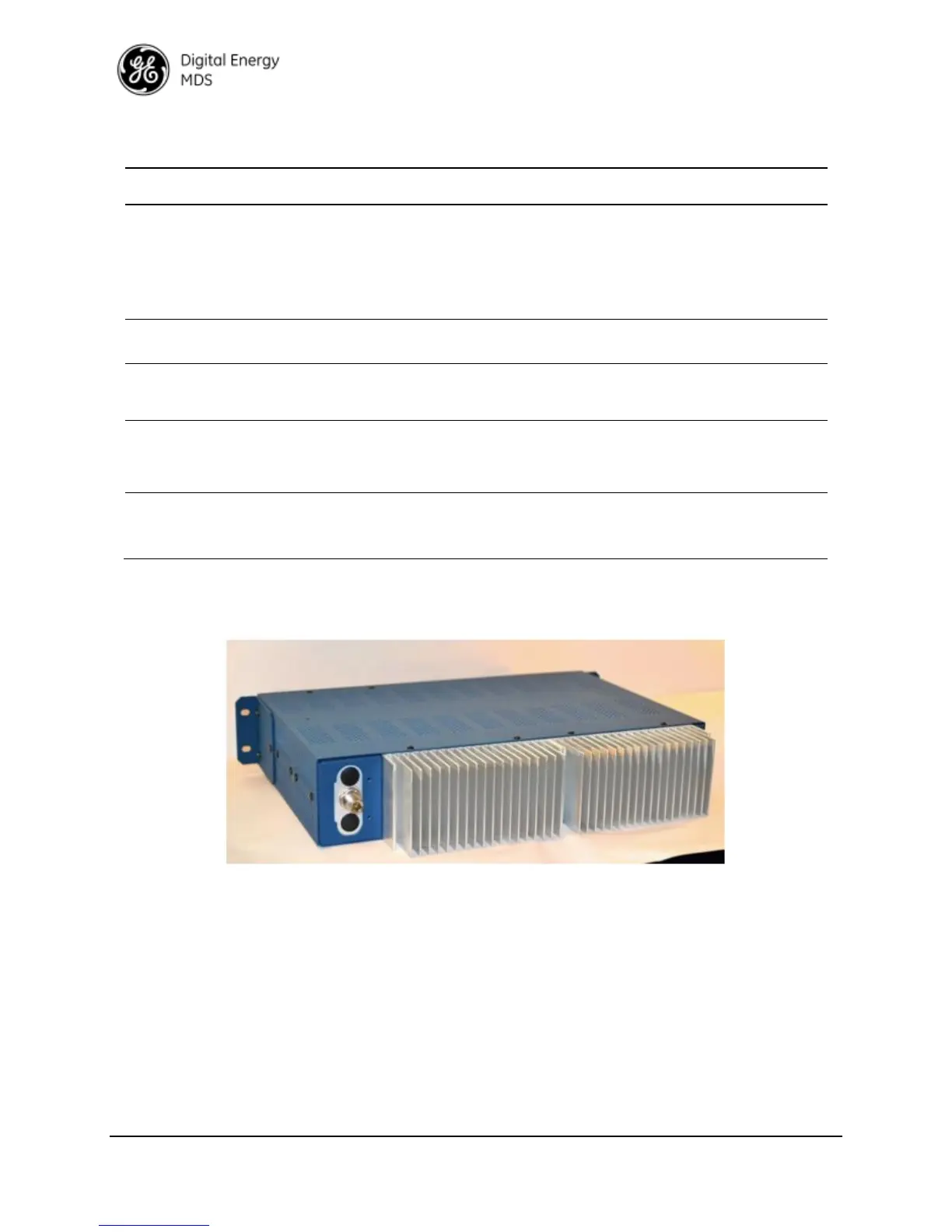
2.4 Rear Antenna Connections
Figure 2-4. MDS™ Master Station, Rear Panel
Showing Antenna Connection & Heatsink
(Other configurations possible for external items such as duplexer or cavity filter)
 Loading...