124 MDS™ Master Station MDS 05-6399A01, Rev. F
9.0 TECHNICAL REFERENCE DATA
9.1 RF Propagation Planning
Establishing a reliable point-to-point radio link requires system planning and design. You should
have an understanding of the physical parameters affecting propagation. The following material
discusses these factors and will assist you in designing a dependable transmission path for your
radio link.
This section is intended for use as a guideline when planning transmission paths. It does
not consider all of the local conditions that may be present, nor does it guarantee that
adequate signal strength will be obtained in a given system. There is no substitute for an
on-the-air test to verify the predicted path results, and to check the overall operation of
the radio system.
To ensure a highly reliable path, a line of sight between both ends of the link is desirable. For
short paths (up to 5 kilometers/3.1 miles), some obstructions might be acceptable, but the
performance of a blocked path is always less predictable than a clear path.
Fresnel Zone Clearance
As the distance spanned by a link gets longer, it is necessary to have more than just a grazing
path between the two ends; the path must clear the ground or other obstacles by some percentage
of a Fresnel zone.
The Fresnel zone corresponds to the width or girth of the radio signal. There are first, second,
and third Fresnel zones, but the first zone is the only one that has substantial effects on signal
strength.
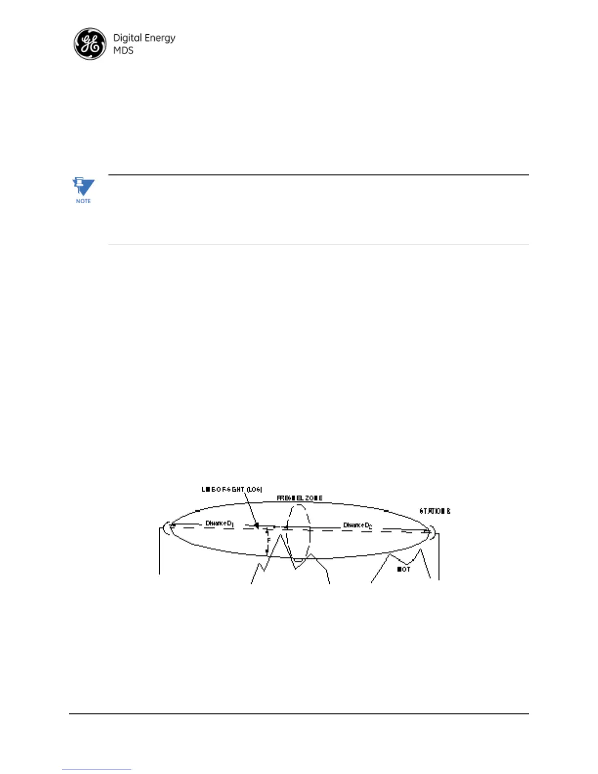
The first Fresnel zone can be visualized as an oval-shaped volume between two station antennas
(Figure 9-1 ). As the width of the radio wave front gets blocked by obstructions, less of the signal
can get to the receiver antenna.
In addition to blocking the signal, obstructions in the first Fresnel zone may also cause multipath
interference due to reflective and refractive signal paths. The reflected or refracted signal might
arrive at the receiver out of phase with the desired signal and cause a canceling effect.
Figure 9-1 Fresnel Zone Obstructions
As a matter of practice, 60 percent of the first Fresnel zone must be clear of obstructions (0.6 x
F) to allow a clear, unobstructed RF path.
Remember, the first Fresnel zone calculation is only one parameter determining path quality.
Earth Curvature
As the distance of a communication link increases, the clearance problem is compounded by the
earth’s curvature. Radio waves traveling through typical atmospheric conditions bend slightly,
which is represented by treating the earth as though it were slightly flatter than it actually is.
 Loading...