EasyManua.ls Logo

GE Grid Solutions MDS Master Station - Grounding Considerations

GE Grid Solutions MDS Master Station
137 pages
Print Icon
To Next Page IconTo Next Page
To Previous Page IconTo Previous Page
Loading...
20 MDS™ Master Station MDS 05-6399A01, Rev. F
Table 3-1. Signal Loss in Coaxial Cables (at 900 MHz)
Cable Type
10 Feet
(3 Meters)
50 Feet
(15 Meters)
100 Feet
(30.5
Meters)
200 Feet
(61 Meters)
RG-8A/U
0.85 dB
4.27 dB
8.54 dB
17.08 dB
1/2 inch HELIAX
0.23 dB
1.15 dB
2.29 dB
4.58 dB
7/8 inch HELIAX
0.13 dB
0.64 dB
1.28 dB
2.56 dB
1-1/4 inch HELIAX
0.10 dB
0.48 dB
0.95 dB
1.90 dB
1-5/8 inch HELIAX
0.08 dB
0.40 dB
0.80 dB
1.60 dB
Table 3-2. Signal Loss in Coaxial Cables (at 400 MHz)
Cable Type
10 Feet
(3 Meters)
50 Feet
(15
Meters)
100 Feet
(30.5
Meters)
200 Feet
(61 Meters)
RG-8A/U
0.51 dB
2.53 dB
5.07 dB
10.14 dB
1/2 inch HELIAX
0.12 dB
0.76 dB
1.51 dB
3.02 dB
7/8 inch HELIAX
0.08 dB
0.42 dB
0.83 dB
1.66 dB
1-1/4 inch HELIAX
0.06 dB
0.31 dB
0.62 dB
1.24 dB
1-5/8 inch HELIAX
0.05 dB
0.26 dB
0.52 dB
1.04 dB
3.5 Grounding Considerations
To minimize the chance of damage to the radio and connected equipment, a safety ground (NEC
Class 2 compliant) is recommended which bonds the Master Station, antenna system, and
connected data equipment to a single-point ground, keeping all ground leads as short as possible.
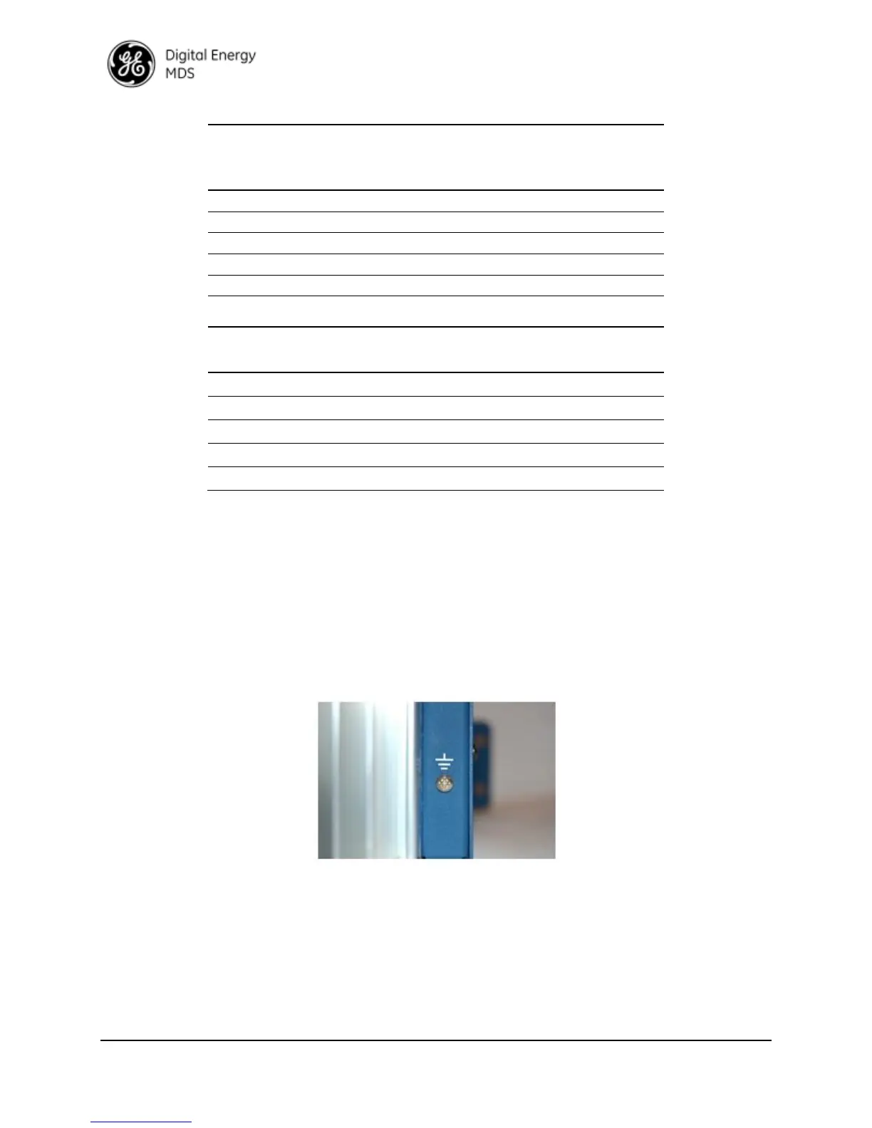
The Master Station should be grounded using the #6-32 screw and star washer provided for this
purpose on the rear panel.
The use of a lightning protector is also recommended where the antenna cable enters the
equipment building; bond the protector to the tower/mast ground, if applicable. All grounds and
cabling must comply with applicable codes and regulations.
Figure 3-2. Rear Panel Grounding Screw

Table of Contents