CHAPTER 12: ABOUT THE MODBUS MEMORY MAP USING THE MEMORY MAP
8 SERIES PROTECTIVE RELAY PLATFORM – COMMUNICATIONS GUIDE 12-9
Using the Memory Map
Reading CO Outputs
CO Outputs are used to show the state of the output relays in the 8-Series device (internal
to the device). For example, on the 869 relay the Trip and Close contacts have voltage
monitoring inputs. The Trip and Close Circuit Monitoring feature uses the voltage input to
monitor the trip and to close coil circuit integrity.
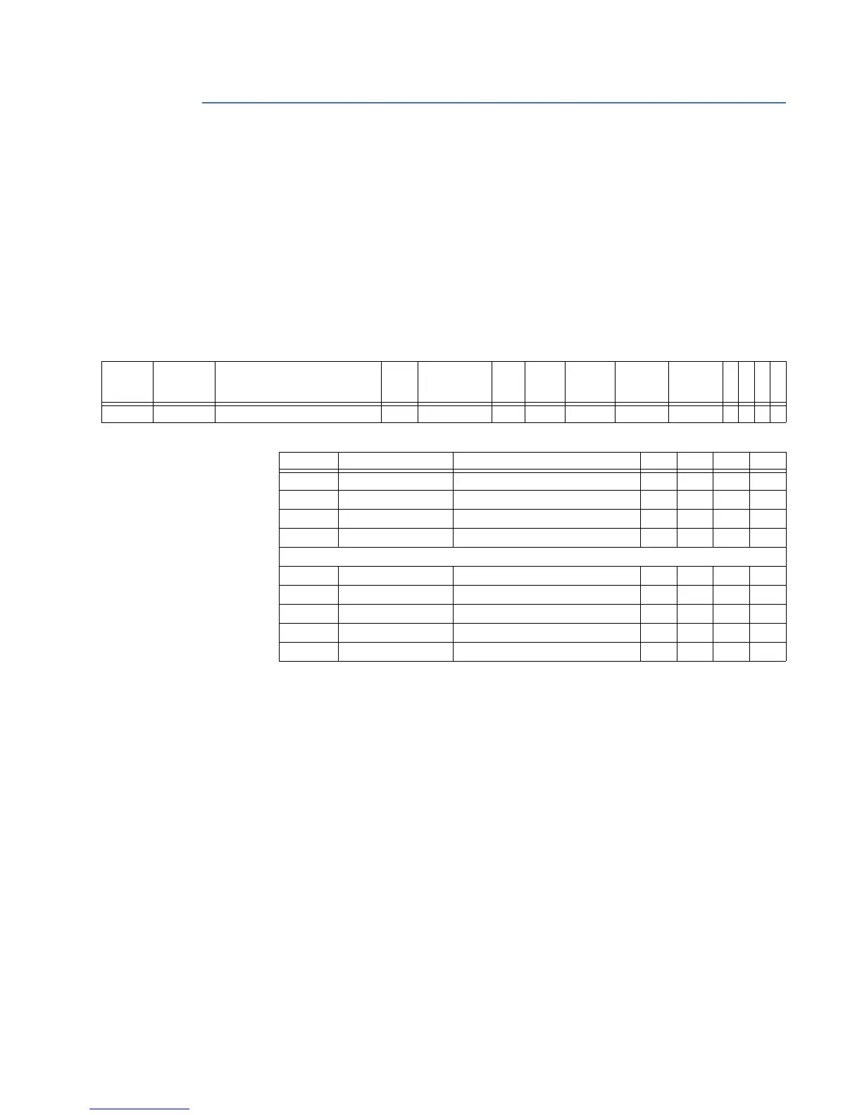
To read the output relay status for all relays, use Modbus address 30706 (0x02C1) where
each bit corresponds to a different output relay as described in format code FC198.
Table 12-5: Modbus Map entry, CO Outputs
Table 12-6: Format Code entries, CO Outputs
Interpreting Element Status for Breaker Contacts
Element Status items with formats FE020 - FE025 are used to sense/verify the state of the
breaker contacts, external to the 8 Series device.
The following Modbus registers are assigned to Breaker Contact Element Status:
• 30765 (0x02FC) Element Status 20 (Output Relay 1)
• 30766 (0x02FD) Element Status 21 (Output Relay 2)
• 30767 (0x02FE) Element Status 22 (Output Relay 3)
• 30768 (0x02FF) Element Status 23 (Output Relay 4)
• 30769 (0x0300) Element Status 24 (Output Relay 5)
• 30770 (0x0301) Element Status 25 (Output Relay 6)
• 30771 (0x0302) Element Status 26 (Critical Fail)
These Modbus Registers are listed in the Modbus memory map table as follows:
Modbus
Address
Hex
Address
Description Min Max Step Units Format
Code
Factory
Default
Size in
Words
8
5
0
8
6
9
8
8
9
8
4
5
30706 0x02C1 CO Outputs 0 0xFFFFFFFF 1 FC198 0 2 Y Y Y Y
Code Type Definition 850 869 889 845
FC126A unsigned 16 bits Off / On Selection
0 Off Y Y Y Y
1 On Y Y Y Y
FC198 unsigned 32 bits Output Relay Operation
Each bit corresponds to a particular output relay, and uses format FC126A
0x00000004 Output Relay 3 Y Y Y Y
0x00000008 Output Relay 4 Y Y Y Y
0x00000010 Output Relay 5 Y Y Y Y
0x00000020 Output Relay 6 Y Y Y Y
0x00000040 Output Relay 7 Y Y Y Y