CHAPTER 12: ABOUT THE MODBUS MEMORY MAP USING THE MEMORY MAP
8 SERIES PROTECTIVE RELAY PLATFORM – COMMUNICATIONS GUIDE 12-11
When the voltage is present on the Trip Contact voltage monitor (Von), the Element Status
21 register will read: 0x2002 (8194). The masked value is then 0x0002, corresponding to
Von in the preceding table.
When the voltage is not present on the Trip Contact voltage monitor (Voff), the Element
Status 21 register will read: 0x2004 (8196). The masked value is then 0x0004,
corresponding to Voff in the preceding table.
Element Status 26 is used to monitor the Critical Fail contact.
When the relay is in service, the "IN SERVICE" LED on the front panel is green.
The Element Status 26 (Critical Fail) register reads: 0x2000 (8192). The masked value is then
0x0000, indicating Critical Fail Op is not present.
When the relay is not service, the "IN SERVICE" LED on the front panel is orange.
The Element Status 26 (Critical Fail) register reads: 0x2002 (8194). The masked value is then
0x0002, corresponding to Cristical Fail Op in the preceding table.
Reading Phase Current Values
In this example a PLC is accessing the 6 sequential values beginning at Modbus address
31270 (Phase A current) in an 850 relay.
The following Modbus registers are assigned to Phase Currents:
• 31270 (0x04F5) J1 Ia - Phase A current
• 31272 (0x04F7) J1 Ib - Phase B current
• 31274 (0x04F9) J1 Ic - Phase C current
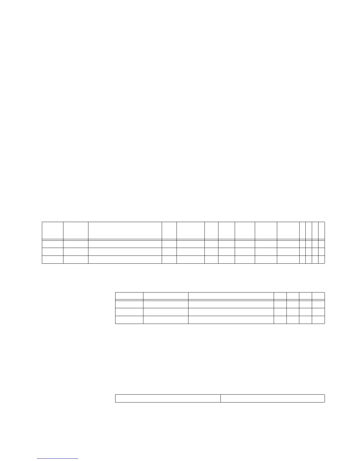
These Modbus Registers are listed in the Modbus memory map table as follows:
Table 12-9: Modbus Map entries for Phase Currents
In this case the format code used is F13, which is described in the Format Code table as
follows:
Table 12-10: Format Code entries for Phase Current
The phase current metering values read by the PLC should match the values shown on the
relay. Validating the received values in the PLC against the real values observed on the 850
relay front panel or read via 8 Series EnerVista Setup is recommended.
PLCs can use two different word orders for reading 32-bit registers. As a result, a 32 bit
value of aabbccdd may be read as aabb ccdd, or as ccdd aabb.
A word-swap may be necessary to read the proper data from 850 relay current registers.
Once the correct word order is set, the obtained value needs to be divided by 1000 to get
the decimal point.
Modbus
Address
Hex
Address
Description Min Max Step Units Format
Code
Factory
Default
Size in
Words
8
5
0
8
6
9
8
8
9
8
4
5
31270 0x04F5 J1 Ia 0 0xFFFFFFFF 1 A F13 0 2 YYYY
31272 0x04F7 J1 Ib 0 0xFFFFFFFF 1 A F13 0 2 YYYY
31274 0x04F9 J1 Ic 0 0xFFFFFFFF 1 A F13 0 2 YYYY
Code Type Definition 850 869 889 845
F13 unsigned 32 bits Unsigned Long Value, 3 Decimal Places
1st 16 bits High Order Word of Long Value Y Y Y Y
2nd 16 bits Low Order Word of Long Value Y Y Y Y
Register: 31270 Register: 312701