GE Multilin F35 Multiple Feeder Protection System 5-43
5 SETTINGS 5.2 PRODUCT SETUP
5
After applying the settings in application example 1, hold down the pushbutton as long as necessary to test all LEDs. Next,
release the pushbutton to automatically start stage 2. Once stage 2 has started, the pushbutton can be released. When
stage 2 is completed, stage 3 will automatically start. The test may be aborted at any time by pressing the pushbutton.
c) TRIP AND ALARM LEDS
PATH: SETTINGS Ö PRODUCT SETUP ÖØ USER-PROGRAMMABLE LEDS ÖØ TRIP & ALARM LEDS
The trip and alarm LEDs are in the first LED column (enhanced faceplate) and on LED panel 1 (standard faceplate). Each
indicator can be programmed to become illuminated when the selected FlexLogic™ operand is in the logic 1 state.
d) USER-PROGRAMMABLE LED 1(48)
PATH: SETTINGS Ö PRODUCT SETUP ÖØ USER-PROGRAMMABLE LEDS ÖØ USER-PROGRAMMABLE LED 1(48)
There are 48 amber LEDs across the relay faceplate LED panels. Each of these indicators can be programmed to illumi-
nate when the selected FlexLogic™ operand is in the logic 1 state.
For the standard faceplate, the LEDs are located as follows.
• LED Panel 2: user-programmable LEDs 1 through 24
• LED Panel 3: user programmable LEDs 25 through 48
For the enhanced faceplate, the LEDs are located as follows.
• LED column 2: user-programmable LEDs 1 through 12
• LED column 3: user-programmable LEDs 13 through 24
• LED column 4: user-programmable LEDs 25 through 36
• LED column 5: user-programmable LEDs 37 through 48
Refer to the LED indicators section in chapter 4 for additional information on the location of these indexed LEDs.
The user-programmable LED settings select the FlexLogic™ operands that control the LEDs. If the
LED 1 TYPE setting is
“Self-Reset” (the default setting), the LED illumination will track the state of the selected LED operand. If the
LED 1 TYPE set-
ting is “Latched”, the LED, once lit, remains so until reset by the faceplate RESET button, from a remote device via a com-
munications channel, or from any programmed operand, even if the LED operand state de-asserts.
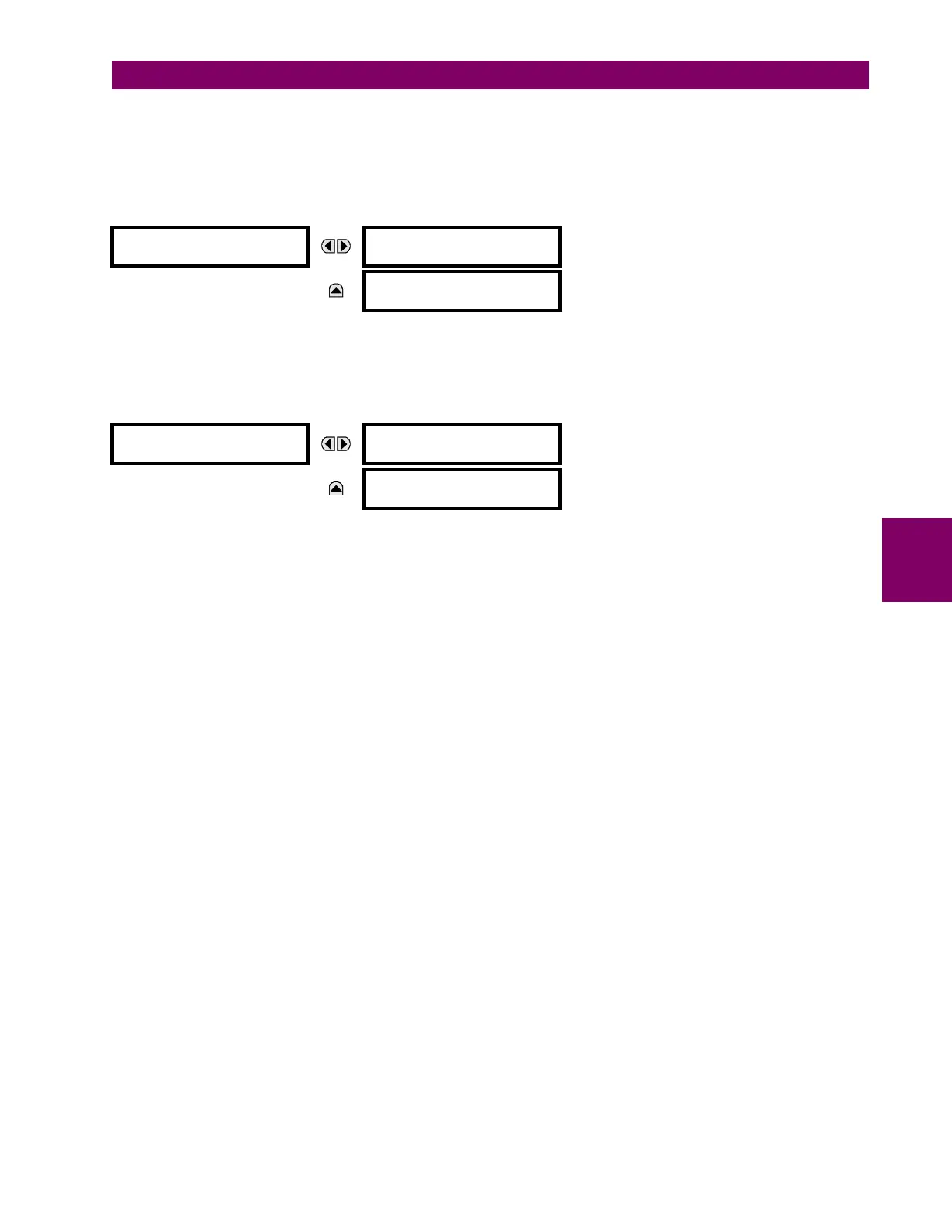
TRIP & ALARM LEDS
TRIP LED INPUT:
Off
Range: FlexLogic™ operand
MESSAGE
ALARM LED INPUT:
Off
Range: FlexLogic™ operand
USER-PROGRAMMABLE
LED 1
LED 1 OPERAND:
Off
Range: FlexLogic™ operand
MESSAGE
LED 1 TYPE:
Self-Reset
Range: Self-Reset, Latched