GE Multilin F35 Multiple Feeder Protection System 5-137
5 SETTINGS 5.6 CONTROL ELEMENTS
5
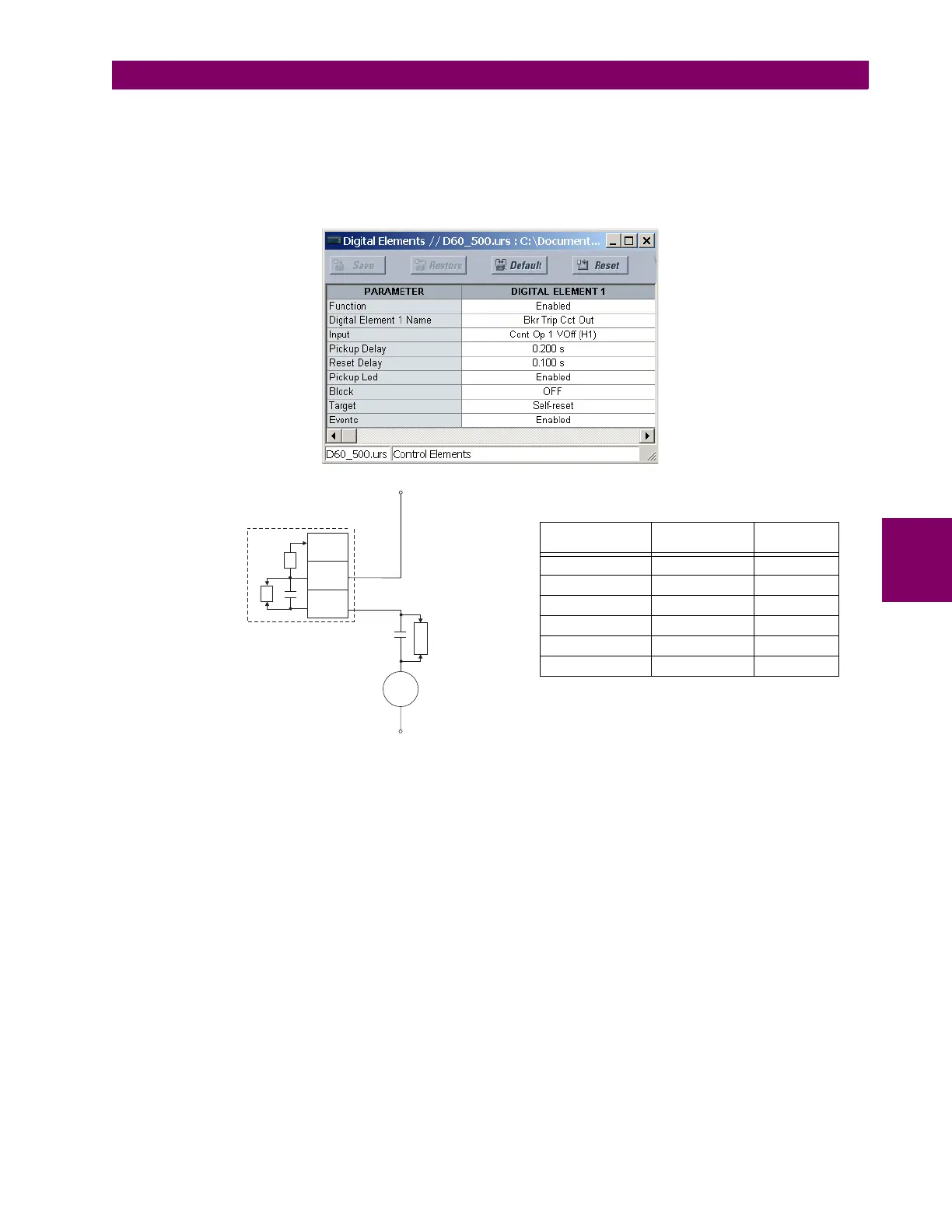
EXAMPLE 2: BREAKER TRIP CIRCUIT INTEGRITY MONITORING
If it is required to monitor the trip circuit continuously, independent of the breaker position (open or closed), a method to
maintain the monitoring current flow through the trip circuit when the breaker is open must be provided (as shown in the fig-
ure below). This can be achieved by connecting a suitable resistor (see figure below) across the auxiliary contact in the trip
circuit. In this case, it is not required to supervise the monitoring circuit with the breaker position – the BLOCK setting is
selected to “Off”. In this case, the settings are as follows (EnerVista UR Setup example shown).
Figure 5–68: TRIP CIRCUIT EXAMPLE 2
Trip
Coil
52a
V
I
H1a
H1c
H1b
UR Relay - Form-A
V = Voltage Monitor
I = Current Monitor
DC+
DC–
827074A2.VSD
R
By-pass
Resistor
Table 5–19: VALUES OF RESISTOR ‘R’
POWER
SUPPLY (V DC)
RESISTANCE
(OHMS)
POWER
(WATTS)
24 1000 2
30 5000 2
48 10000 2
110 25000 5
125 25000 5
250 50000 5