5-158 F35 Multiple Feeder Protection System GE Multilin
5.7 INPUTS/OUTPUTS 5 SETTINGS
5
• Setting REMOTE IN 1 DEFAULT STATE to “On” value defaults the input to logic 1.
• Setting
REMOTE IN 1 DEFAULT STATE to “Off” value defaults the input to logic 0.
• Setting REMOTE IN 1 DEFAULT STATE to “Latest/On” freezes the input in case of lost communications. If the latest state is
not known, such as after relay power-up but before the first communication exchange, the input will default to logic 1.
When communication resumes, the input becomes fully operational.
• Setting REMOTE IN 1 DEFAULT STATE to “Latest/Off” freezes the input in case of lost communications. If the latest state is
not known, such as after relay power-up but before the first communication exchange, the input will default to logic 0.
When communication resumes, the input becomes fully operational.
For additional information on GSSE/GOOOSE messaging, refer to the Remote devices section in this chap-
ter.
5.7.7 REMOTE OUTPUTS
a) DNA BIT PAIRS
PATH: SETTINGS ÖØ INPUTS/OUTPUTS ÖØ REMOTE OUTPUTS DNA BIT PAIRS Ö REMOTE OUPUTS DNA- 1(32) BIT PAIR
Remote outputs (1 to 32) are FlexLogic™ operands inserted into GSSE/GOOSE messages that are transmitted to remote
devices on a LAN. Each digital point in the message must be programmed to carry the state of a specific FlexLogic™ oper-
and. The above operand setting represents a specific DNA function (as shown in the following table) to be transmitted.
b) USERST BIT PAIRS
PATH: SETTINGS ÖØ INPUTS/OUTPUTS ÖØ REMOTE OUTPUTS UserSt BIT PAIRS Ö REMOTE OUTPUTS UserSt- 1(32) BIT PAIR
Remote outputs 1 to 32 originate as GSSE/GOOSE messages to be transmitted to remote devices. Each digital point in the
message must be programmed to carry the state of a specific FlexLogic™ operand. The setting above is used to select the
operand which represents a specific UserSt function (as selected by the user) to be transmitted.
The following setting represents the time between sending GSSE/GOOSE messages when there has been no change of
state of any selected digital point. This setting is located in the
PRODUCT SETUP ÖØ COMMUNICATIONS ÖØ IEC 61850 PROTO-
COL
ÖØ GSSE/GOOSE CONFIGURATION settings menu.
For more information on GSSE/GOOSE messaging, refer to Remote Inputs/Outputs Overview in the
Remote Devices section.
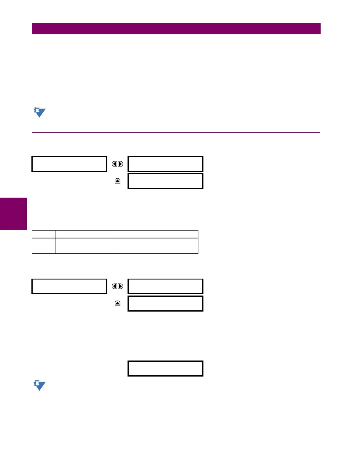
REMOTE OUTPUTS
DNA- 1 BIT PAIR
DNA- 1 OPERAND:
Off
Range: FlexLogic™ operand
MESSAGE
DNA- 1 EVENTS:
Disabled
Range: Disabled, Enabled
Table 5–20: IEC 61850 DNA ASSIGNMENTS
DNA IEC 61850 DEFINITION FLEXLOGIC™ OPERAND
1 Test IEC 61850 TEST MODE
2 ConfRev IEC 61850 CONF REV
REMOTE OUTPUTS
UserSt- 1 BIT PAIR
UserSt- 1 OPERAND:
Off
Range: FlexLogic™ operand
MESSAGE
UserSt- 1 EVENTS:
Disabled
Range: Disabled, Enabled
DEFAULT GSSE/GOOSE
UPDATE TIME: 60 s
Range: 1 to 60 s in steps of 1