5-160 F35 Multiple Feeder Protection System GE Multilin
5.7 INPUTS/OUTPUTS 5 SETTINGS
5
b) DIRECT OUTPUTS
PATH: SETTINGS ÖØ INPUTS/OUTPUTS ÖØ DIRECT OUTPUTS Ö DIRECT OUTPUT 1(32)
The DIRECT OUT 1 NAME setting allows the user to assign a descriptive name to the direct output. The DIR OUT 1 OPERAND is
the FlexLogic™ operand that determines the state of this direct output.
c) APPLICATION EXAMPLES
The examples introduced in the earlier Direct inputs and outputs section (part of the Product Setup section) are continued
below to illustrate usage of the direct inputs and outputs.
EXAMPLE 1: EXTENDING INPUT/OUTPUT CAPABILITIES OF A F35 RELAY
Consider an application that requires additional quantities of digital inputs or output contacts or lines of programmable logic
that exceed the capabilities of a single UR-series chassis. The problem is solved by adding an extra UR-series IED, such
as the C30, to satisfy the additional inputs/outputs and programmable logic requirements. The two IEDs are connected via
single-channel digital communication cards as shown below.
Figure 5–79: INPUT AND OUTPUT EXTENSION VIA DIRECT INPUTS AND OUTPUTS
Assume contact input 1 from UR IED 2 is to be used by UR IED 1. The following settings should be applied (Direct Input 5
and bit number 12 are used, as an example):
The Cont Ip 1 On operand of UR IED 2 is now available in UR IED 1 as DIRECT INPUT 5 ON.
EXAMPLE 2: INTERLOCKING BUSBAR PROTECTION
A simple interlocking busbar protection scheme can be accomplished by sending a blocking signal from downstream
devices, say 2, 3 and 4, to the upstream device that monitors a single incomer of the busbar, as shown in the figure below.
Figure 5–80: SAMPLE INTERLOCKING BUSBAR PROTECTION SCHEME
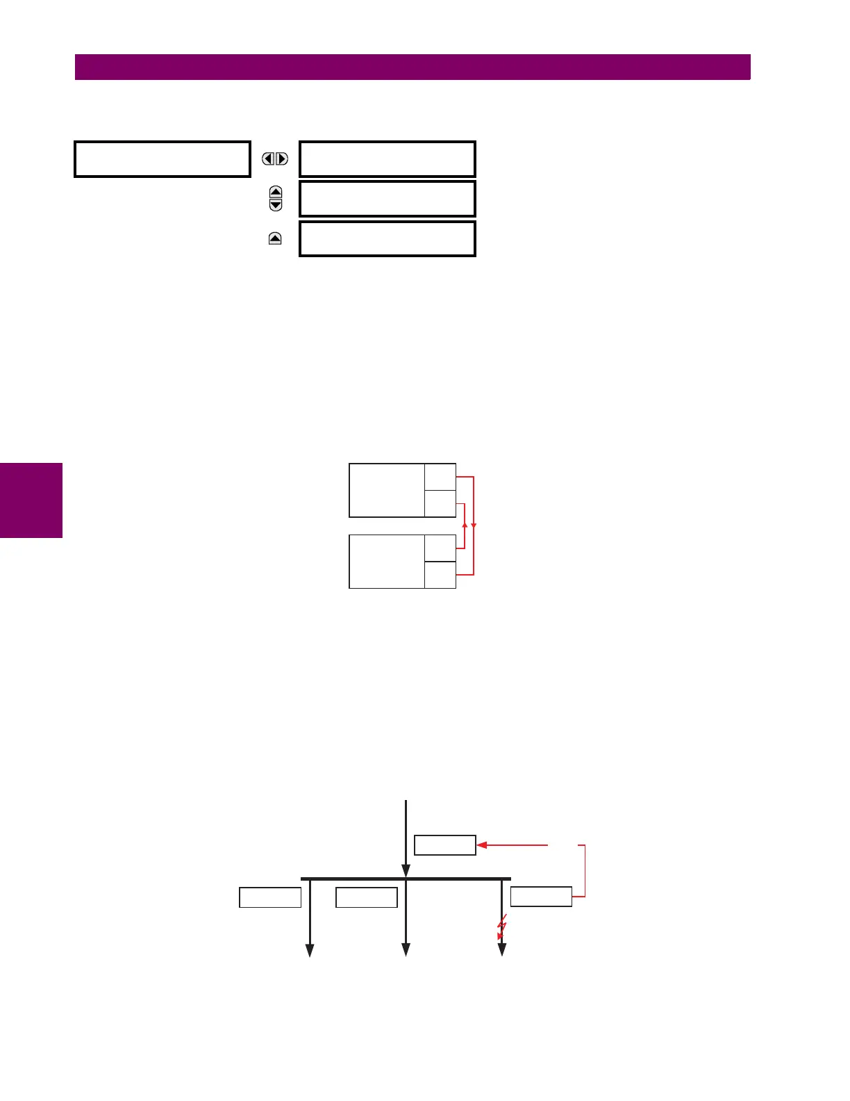
DIRECT OUTPUT 1
DIRECT OUT 1 NAME:
Dir Out 1
Range: up to 12 alphanumeric characters
MESSAGE
DIRECT OUT 1 OPERAND:
Off
Range: FlexLogic™ operand
MESSAGE
DIRECT OUTPUT 1
EVENTS: Disabled
Range: Enabled, Disabled
UR IED 1: DIRECT INPUT 5 DEVICE ID = “2”
DIRECT INPUT 5 BIT NUMBER = “12”
UR IED 2:
DIRECT OUT 12 OPERAND = “Cont Ip 1 On”
UR IED 1
TX1
RX1
UR IED 2
TX1
RX1
842712A1.CDR
UR IED 1
UR IED 2
UR IED 4
UR IED 3
BLOCK