5-162 F35 Multiple Feeder Protection System GE Multilin
5.7 INPUTS/OUTPUTS 5 SETTINGS
5
In the above architecture, Devices 1 and 3 do not communicate directly. Therefore, Device 2 must act as a ‘bridge’. The fol-
lowing settings should be applied:
UR IED 1: DIRECT OUT 2 OPERAND: "HYB POTT TX1"
DIRECT INPUT 5 DEVICE ID: "2"
DIRECT INPUT 5 BIT NUMBER: "2" (this is a message from IED 2)
DIRECT INPUT 6 DEVICE ID: "2"
DIRECT INPUT 6 BIT NUMBER: "4" (effectively, this is a message from IED 3)
UR IED 3: DIRECT OUT 2 OPERAND: "HYB POTT TX1"
DIRECT INPUT 5 DEVICE ID: "2"
DIRECT INPUT 5 BIT NUMBER: "2" (this is a message from IED 2)
DIRECT INPUT 6 DEVICE ID: "2"
DIRECT INPUT 6 BIT NUMBER: "3" (effectively, this is a message from IED 1)
UR IED 2: DIRECT INPUT 5 DEVICE ID: "1"
DIRECT INPUT 5 BIT NUMBER: "2"
DIRECT INPUT 6 DEVICE ID: "3"
DIRECT INPUT 6 BIT NUMBER: "2"
DIRECT OUT 2 OPERAND: "HYB POTT TX1"
DIRECT OUT 3 OPERAND: "DIRECT INPUT 5" (forward a message from 1 to 3)
DIRECT OUT 4 OPERAND: "DIRECT INPUT 6" (forward a message from 3 to 1)
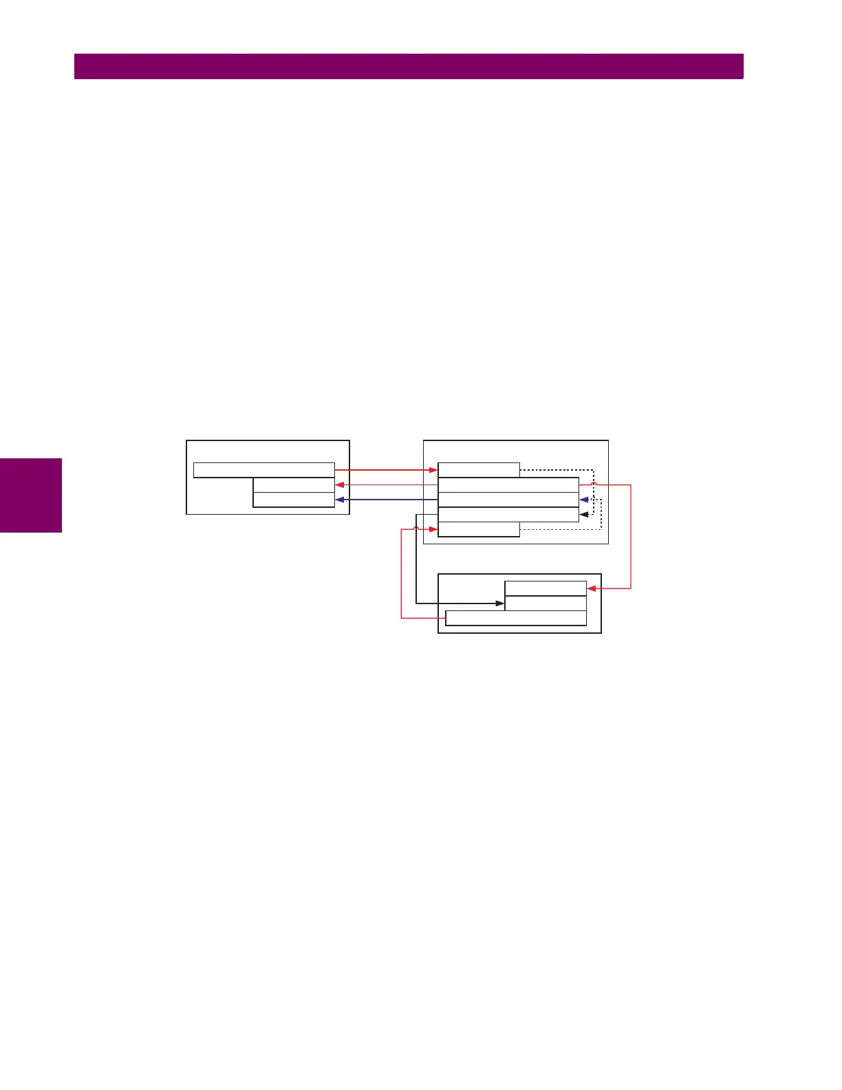
Signal flow between the three IEDs is shown in the figure below:
Figure 5–83: SIGNAL FLOW FOR DIRECT INPUT AND OUTPUT – EXAMPLE 3
In three-terminal applications, both the remote terminals must grant permission to trip. Therefore, at each terminal, direct
inputs 5 and 6 should be ANDed in FlexLogic™ and the resulting operand configured as the permission to trip (
HYB POTT
RX1
setting).
842717A1.CDR
UR IED 3
UR IED 2UR IED 1
DIRECT OUT 2 = HYB POTT TX1
DIRECT INPUT 5
DIRECT INPUT 6
DIRECT OUT 2 = HYB POTT TX1
DIRECT INPUT 5
DIRECT INPUT 6
DIRECT OUT 2 = HYB POTT TX1
DIRECT INPUT 6
DIRECT OUT 4 = DIRECT INPUT 6
DIRECT OUT 3 = DIRECT INPUT 5
DIRECT INPUT 5