GE Multilin F35 Multiple Feeder Protection System B-37
APPENDIX B B.4 MEMORY MAPPING
B
9B95 Teleprotection Network Status 0 to 2 --- 1 F134 2 (n/a)
9BA0 Teleprotection Channel 1 Input States 0 to 1 --- 1 F500 0
9BA1 Teleprotection Channel 2 Input States 0 to 1 --- 1 F500 0
9BB0 Teleprotection Input 1 States, 1 per register (16 items) 0 to 1 --- 1 F108 0 (Off)
9BC0 Teleprotection Input 2 States, 1 per register (16 items) 0 to 1 --- 1 F108 0 (Off)
Selector switch actual values (read only)
A210 Selector switch 1 position 1 to 7 --- 1 F001 0
A211 Selector switch 2 position 1 to 7 --- 1 F001 1
Selector switch settings (read/write, 2 modules)
A280 Selector 1 Function 0 to 1 --- 1 F102 0 (Disabled)
A281 Selector 1 Range 1 to 7 --- 1 F001 7
A282 Selector 1 Timeout 3 to 60 s 0.1 F001 50
A283 Selector 1 Step Up 0 to 65535 --- 1 F300 0
A284 Selector 1 Step Mode 0 to 1 --- 1 F083 0 (Time-out)
A285 Selector 1 Acknowledge 0 to 65535 --- 1 F300 0
A286 Selector 1 Bit0 0 to 65535 --- 1 F300 0
A287 Selector 1 Bit1 0 to 65535 --- 1 F300 0
A288 Selector 1 Bit2 0 to 65535 --- 1 F300 0
A289 Selector 1 Bit Mode 0 to 1 --- 1 F083 0 (Time-out)
A28A Selector 1 Bit Acknowledge 0 to 65535 --- 1 F300 0
A28B Selector 1 Power Up Mode 0 to 2 --- 1 F084 0 (Restore)
A28C Selector 1 Target 0 to 2 --- 1 F109 0 (Self-reset)
A28D Selector 1 Events 0 to 1 --- 1 F102 0 (Disabled)
A28E Reserved (10 items) --- --- 1 F001 0
A298 ...Repeated for Selector 2
DNP/IEC Points (Read/Write Setting)
A300 DNP/IEC 60870-5-104 Binary Input Points (256 items) 0 to 65535 --- 1 F300 0
A400 DNP/IEC 60870-5-104 Analog Input Points (256 items) 0 to 65535 --- 1 F300 0
Flexcurves C and D (Read/Write Setting)
A600 FlexCurve C (120 items) 0 to 65535 ms 1 F011 0
A680 FlexCurve D (120 items) 0 to 65535 ms 1 F011 0
Non Volatile Latches (Read/Write Setting) (16 modules)
A700 Non-Volatile Latch 1 Function 0 to 1 --- 1 F102 0 (Disabled)
A701 Non-Volatile Latch 1 Type 0 to 1 --- 1 F519 0 (Reset Dominant)
A702 Non-Volatile Latch 1 Set 0 to 65535 --- 1 F300 0
A703 Non-Volatile Latch 1 Reset 0 to 65535 --- 1 F300 0
A704 Non-Volatile Latch 1 Target 0 to 2 --- 1 F109 0 (Self-reset)
A705 Non-Volatile Latch 1 Events 0 to 1 --- 1 F102 0 (Disabled)
A706 Reserved (4 items) --- --- --- F001 0
A70A ...Repeated for Non-Volatile Latch 2
A714 ...Repeated for Non-Volatile Latch 3
A71E ...Repeated for Non-Volatile Latch 4
A728 ...Repeated for Non-Volatile Latch 5
A732 ...Repeated for Non-Volatile Latch 6
A73C ...Repeated for Non-Volatile Latch 7
A746 ...Repeated for Non-Volatile Latch 8
A750 ...Repeated for Non-Volatile Latch 9
A75A ...Repeated for Non-Volatile Latch 10
A764 ...Repeated for Non-Volatile Latch 11
A76E ...Repeated for Non-Volatile Latch 12
A778 ...Repeated for Non-Volatile Latch 13
A782 ...Repeated for Non-Volatile Latch 14
A78C ...Repeated for Non-Volatile Latch 15
A796 ...Repeated for Non-Volatile Latch 16
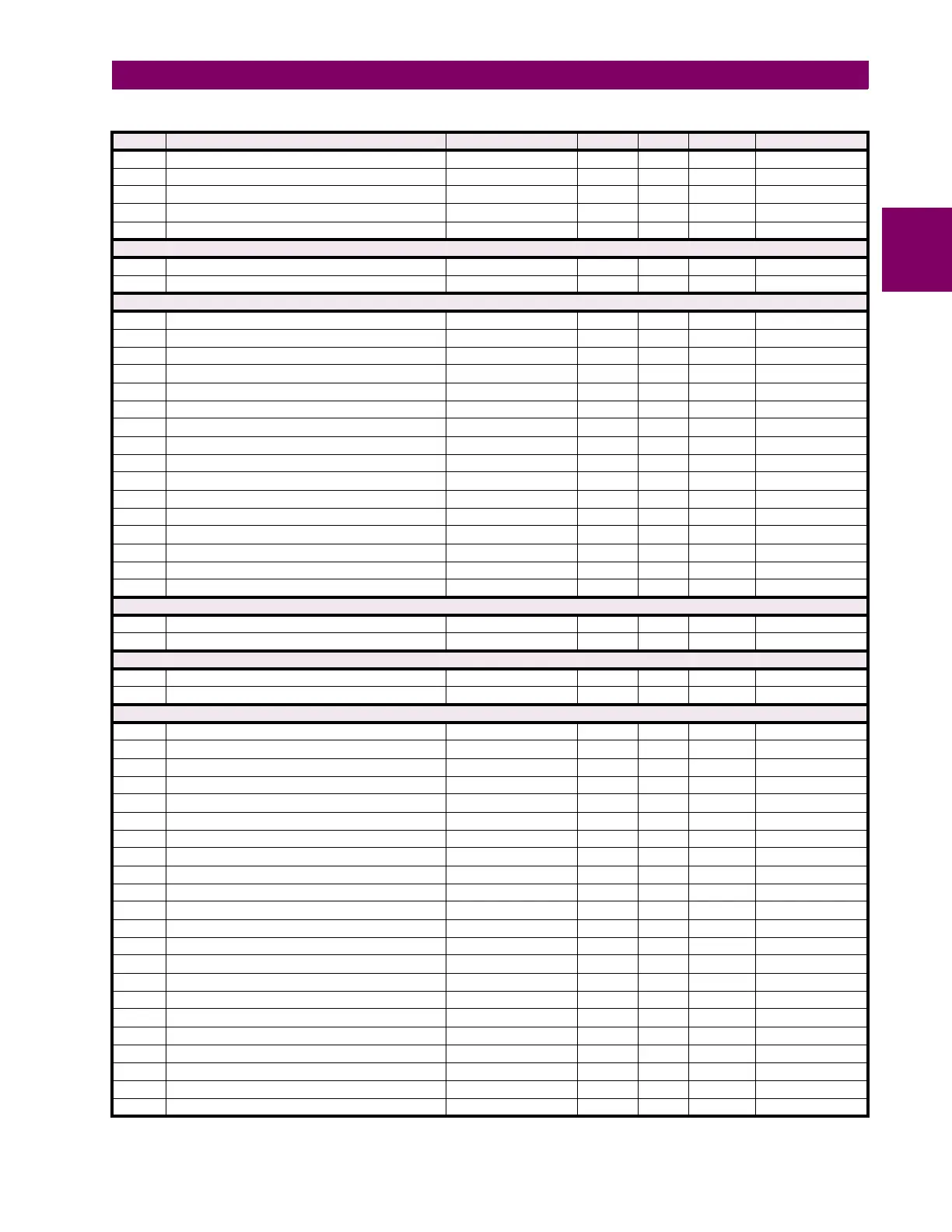
Table B–9: MODBUS MEMORY MAP (Sheet 30 of 48)
ADDR REGISTER NAME RANGE UNITS STEP FORMAT DEFAULT