1200C-2000C Fire Alarm Control Panel, Repeater, and Black Box Installation Manual 21
Fault relay connection on the PS1200N
Configure the power supply fault relays using jumpers J7 and J8 beside the fault
output (see Figure 18 on page 20).
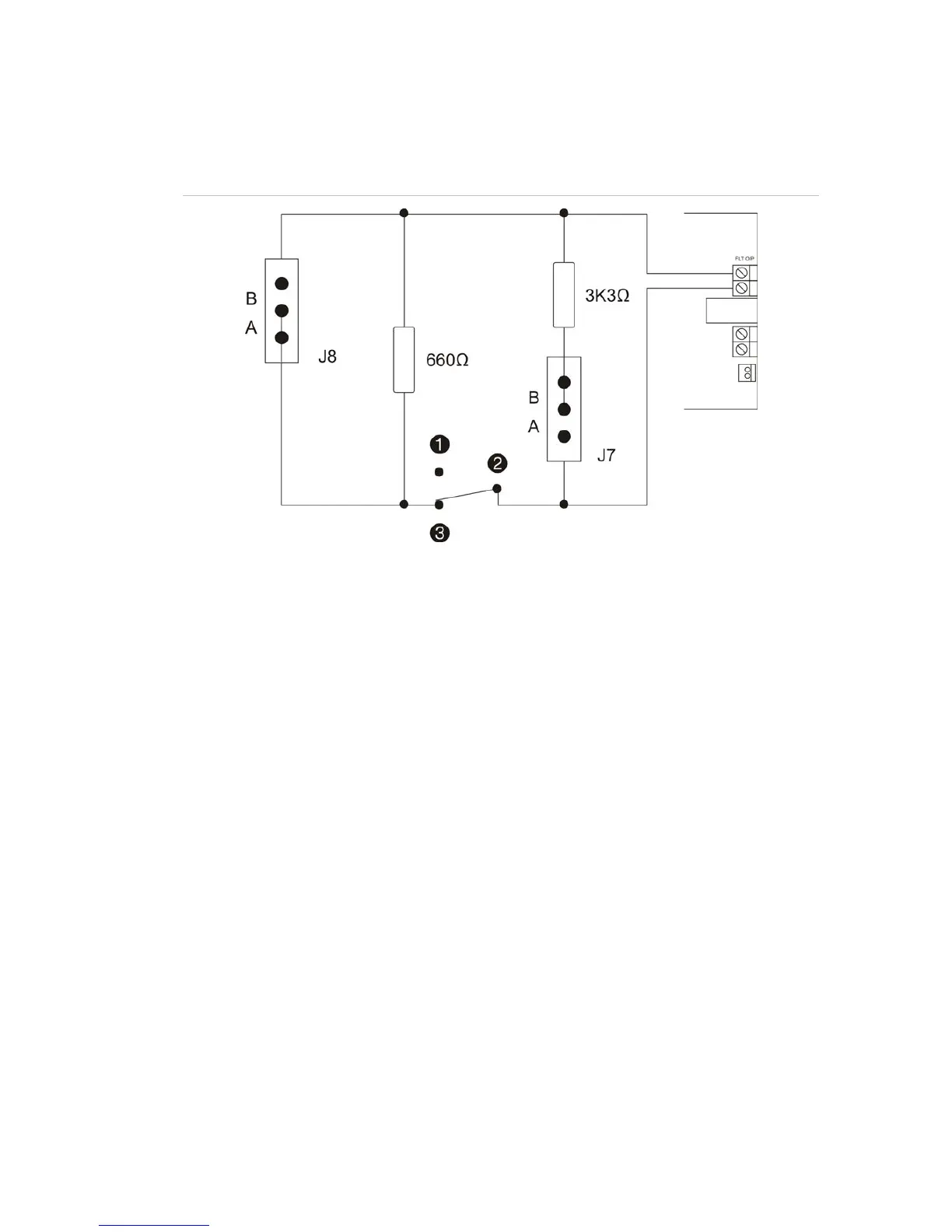
Figure 19: PS1200N fault relay jumper configurations
1. Normally open (NO)
2. Common (C)
3. Normally closed (NC)
Note: Components shown are mounted onto the PS1200N PCB and do not represent
field wiring.
The fault output is normally closed. The default setting for jumpers J7 and J8 is A.
Configuration options are:
J7 (pins for position B connected on PCB)
• Position A = 3K3
• Position B = 0
J8 (pins for position A connected on PCB)
• Position A = 660
• Position B = 0
 Loading...


