6-62 469 Motor Management Relay GE Power Management
6.4 MEMORY MAP 6 COMMUNICATIONS
6
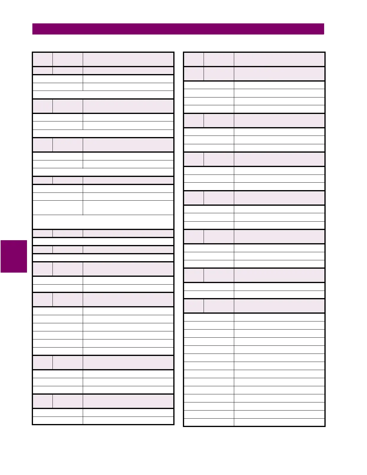
F20 32 bits 2’s COMPLEMENT SIGNED LONG VALUE
1st 16 bits High Order Word of Long Value
2nd 16 bits Low Order Word of Long Value
Note: -1 means “Never”
F21 16 bits 2’s COMPLEMENT SIGNED VALUE
2 DECIMAL PLACES (Power Factor)
< 0 Leading Power Factor - Negative
> 0 Lagging Power Factor - Positive
Example: Power Factor of 0.87 lag is used as 87 (i.e. 0057)
F22 16 bits TWO 8-BIT CHARACTERS
PACKED INTO 16-BIT UNSIGNED
MSB First Character
LSB Second Character
Example: String ‘AB’ stored as 4142 hex.
F24 32 bits TIME FORMAT FOR BROADCAST
1
st
byte Hours (0 to 23)
2
nd
byte Minutes (0 to 59)
3
rd
& 4
th
bytes Milliseconds (0 to 59999)
Note: Clock resolution limited to 0.01 sec
Example: 1:15:48:572 stored as 17808828
(i.e., 1
st
word 010F, 2
nd
word BDBC)
F25 16 bits UNSIGNED VALUE, 4 DECIMAL PLACES
Example: 0.1234 stored as 1234
F26 16 bits UNSIGNED VALUE, 3 DECIMAL PLACES
Example: 1.234 stored as 1234
FC100 Unsigned
16 bit integer
TEMPEATURE DISPLAY UNITS
0Celsius
1Fahrenheit
FC101 Unsigned
16 bit integer
RS 485 BAUD RATE
0 300 baud
1 1200 baud
2 2400 baud
3 4800 baud
4 9600 baud
5 19200 baud
FC102 Unsigned
16 bit integer
RS 485 PARITY
0None
1Odd
2Even
FC103 Unsigned
16 bit integer
OFF / ON or NO/YES SELECTION
0Off / No
1On / Yes
Table 6–2: MEMORY MAP DATA FORMATS (Sheet 3 of 14)
FORMAT
CODE
TYPE DEFINITION
FC104 Unsigned
16 bit integer
GROUND CT TYPE
0None
11 A Secondary
25 A Secondary
3 50/0.025 CT
FC105 Unsigned
16 bit integer
DIFFERENTIAL CT TYPE
0None
11 A Secondary
25 A Secondary
FC106 Unsigned
16 bit integer
VOLTAGE TRANSFORMER CONNECTION
TYPE
0None
1Open Delta
2Wye
FC107 Unsigned
16 bit integer
NOMINAL FREQUENCY
060 Hz
150 Hz
2Variable
FC108 Unsigned
16 bit integer
REDUCED VOLTAGE STARTING TRANSITION
ON
0 Current Only
1 Current or Timer
2 Current and Timer
FC109 Unsigned
16 bit integer
STARTER STATUS SWITCH
0Starter Aux a
1Starter Aux b
FC110 Unsigned
16 bit integer
ASSIGNABLE INPUT FUNCTION
0Off
1 Remote Alarm
2 Remote Trip
3 Speed Switch Trip
4Load Shed Trip
5 Pressure Sw. Alarm
6Pressure Switch Trip
7 Vibration Sw. Alarm
8 Vibration Sw. Trip
9 Digital Counter
10 Tachometer
11 General Sw. A
12 General Sw. B
13 General Sw. C
Table 6–2: MEMORY MAP DATA FORMATS (Sheet 4 of 14)
FORMAT
CODE
TYPE DEFINITION

 Loading...


