GE Power Management 469 Motor Management Relay A-5
APPENDIX A A.1 COMMISSIONING
A
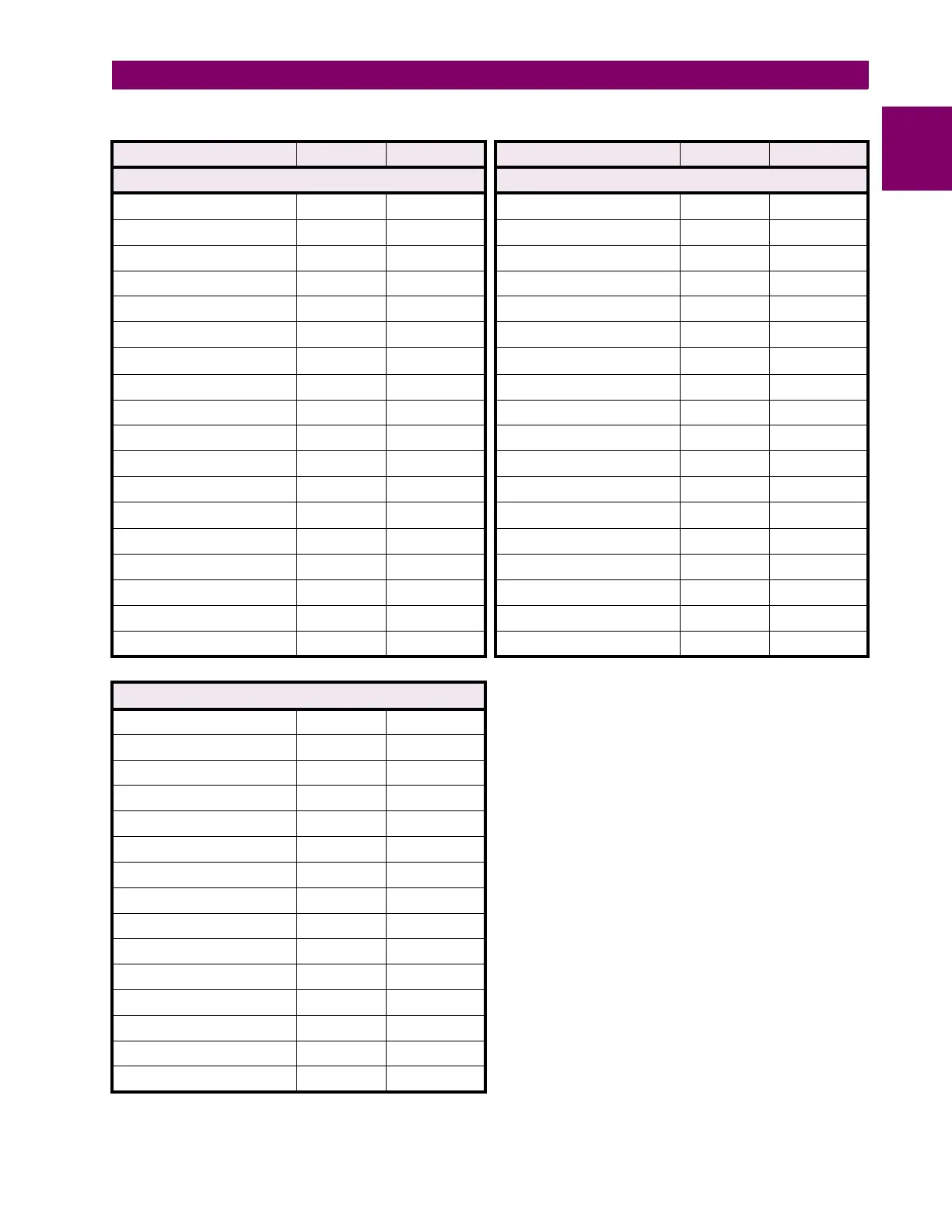
Table A–5: SETPOINTS PAGE 5 – PROTECTION
DESCRIPTION DEFAULT USER VALUE DESCRIPTION DEFAULT USER VALUE
O/L CURVE SETUP O/L CURVE SETUP
Standard O/L Curve No. 4 Time to Trip @ 4.25 x FLA 20.5 s
Time to Trip @ 1.01 x FLA 17414.5 s Time to Trip @ 5.00 x FLA 14.6 s
Time to Trip @ 1.05 x FLA 3414.9 s Time to Trip @ 5.50 x FLA 12.0 s
Time to Trip @ 1.10 x FLA 1666.7 s Time to Trip @ 6.00 x FLA 10.0 s
Time to Trip @ 1.20 x FLA 795.4 s Time to Trip @ 6.50 x FLA 8.5 s
Time to Trip @ 1.30 x FLA 507.2 s Time to Trip @ 7.00 x FLA 7.3 s
Time to Trip @ 1.40 x FLA 364.6 s Time to Trip @ 7.50 x FLA 6.3 s
Time to Trip @ 1.50 x FLA 280.0 s Time to Trip @ 8.00 x FLA 5.6 s
Time to Trip @ 1.75 x FLA 169.7 s Time to Trip @ 10.00 x FLA
5.6
s
Time to Trip @ 2.00 x FLA 116.6 s Time to Trip @ 15.00 x FLA 5.6 s
Time to Trip @ 2.25 x FLA 86.1 s Time to Trip @ 20.00 x FLA 5.6 s
Time to Trip @ 2.50 x FLA 66.6 s Min. Allowable Line Voltage 80%
Time to Trip @ 2.75 x FLA 53.3 s Stall Current @ Min. Vline 4.80 x FLA
Time to Trip @ 3.00 x FLA 43.7 s Safe Stall Time @ Min. Vline 20.0 s
Time to Trip @ 3.25 x FLA 36.6 s Accel. Intersect @ Min. Vline 3.80 x FLA
Time to Trip @ 3.50 x FLA 31.1 s Stall Current @ 100% Vline 6.00 x FLA
Time to Trip @ 3.75 x FLA 26.8 s Safe Stall Time @ 100% Vline 10.0 s
Time to Trip @ 4.00 x FLA 23.3 s Accel. Intersect @ 100% Vline 5.00 x FLA
THERMAL MODEL
Select Curve Style Standard
Overload Pickup Level 1.01 x FLA
Assign Trip Relays Trip
Unbalance Bias K Factor 0
Cool Time Constant Running 15 min.
Cool Time Constant Stopped 30 min.
Hot/Cold Safe Stall Ratio 1.00
Enable RTD Biasing? No
RTD Bias Minimum 40°C
RTD Bias Center 130°C
RTD Bias Maximum 155°C
Thermal Capacity Alarm Off
Assign Alarm Relays Alarm
Thermal Cap. Alarm Level 75% Used
Thermal Cap. Alarm Events Off

 Loading...


